Infiniti FX35, FX50 (S51). Manual — part 806

P0037, P0038, P0057, P0058 HO2S2 HEATER
EC-765
< DTC/CIRCUIT DIAGNOSIS >
[VK50VE]
C
D
E
F
G
H
I
J
K
L
M
A
EC
N
P
O
YES
>> GO TO 5.
NO
>> Repair open circuit, short to ground or short to power in harness or connectors.
5.
CHECK HO2S2 HEATER
EC-765, "Component Inspection"
Is the inspection result normal?
YES
>> GO TO 7.
NO
>> GO TO 6.
6.
REPLACE HEATED OXYGEN SENSOR 2
Replace malfunctioning heated oxygen sensor 2.
CAUTION:
• Discard any heated oxygen sensor which has been dropped from a height of more than 0.5 m (19.7
in) onto a hard surface such as a concrete floor; use a new one.
• Before installing new oxygen sensor, clean exhaust system threads using Oxygen Sensor Thread
Cleaner [commercial service tool (J-43897-18 or J-43897-12)] and approved anti-seize lubricant
(commercial service tool).
>> INSPECTION END
7.
CHECK INTERMITTENT INCIDENT
GI-36, "Intermittent Incident"
.
>> INSPECTION END
Component Inspection
INFOID:0000000005237245
1.
CHECK HEATED OXYGEN SENSOR 2 HEATER
1.
Turn ignition switch OFF.
2.
Disconnect heated oxygen sensor 2 (HO2S2) harness connector.
3.
Check resistance between HO2S2 terminals as follows.
Is the inspection result normal?
YES
>> INSPECTION END
NO
>> GO TO 2.
2.
REPLACE HEATED OXYGEN SENSOR 2
Replace malfunctioning heated oxygen sensor 2.
CAUTION:
• Discard any heated oxygen sensor which has been dropped from a height of more than 0.5 m (19.7
in) onto a hard surface such as a concrete floor; use a new one.
• Before installing new oxygen sensor, clean exhaust system threads using Oxygen Sensor Thread
Cleaner [commercial service tool (J-43897-18 or J-43897-12)] and approved anti-seize lubricant
(commercial service tool).
>> INSPECTION END
Terminal
Resistance
2 and 3
3.4 - 4.4
Ω
[at 25
°
C (77
°
F)]
1 and 2, 3, 4
∞
Ω
(Continuity should not exist)
4 and 1, 2, 3
EC-766
< DTC/CIRCUIT DIAGNOSIS >
[VK50VE]
P0075, P0081 IVT CONTROL SOLENOID VALVE
P0075, P0081 IVT CONTROL SOLENOID VALVE
Description
INFOID:0000000005237246
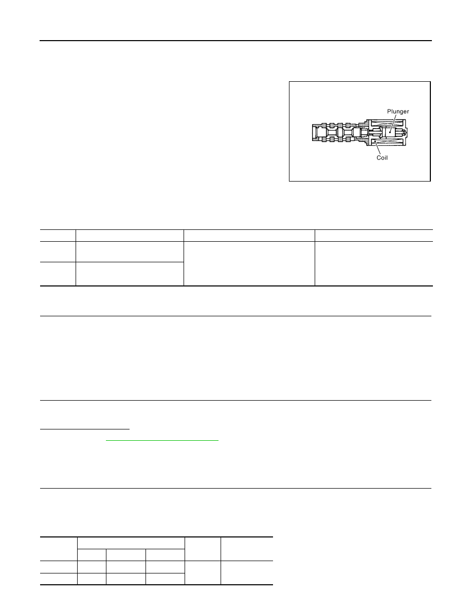
Intake valve timing control solenoid valve is activated by ON/OFF
pulse duty (ratio) signals from the ECM.
The intake valve timing control solenoid valve changes the oil
amount and direction of flow through intake valve timing control unit
or stops oil flow.
The longer pulse width advances valve angle.
The shorter pulse width retards valve angle.
When ON and OFF pulse widths become equal, the solenoid valve
stops oil pressure flow to fix the intake valve angle at the control
position.
DTC Logic
INFOID:0000000005237247
DTC DETECTION LOGIC
DTC CONFIRMATION PROCEDURE
1.
PRECONDITIONING
If DTC Confirmation Procedure has been previously conducted, always perform the following procedure
before conducting the next test.
1.
Turn ignition switch OFF and wait at least 10 seconds.
2.
Turn ignition switch ON.
3.
Turn ignition switch OFF and wait at least 10 seconds.
>> GO TO 2.
2.
PERFORM DTC CONFIRMATION PROCEDURE
1.
Start engine and let it idle for 5 seconds.
2.
Check 1st trip DTC.
Is 1st trip DTC detected?
YES
>> Go to
NO
>> INSPECTION END
Diagnosis Procedure
INFOID:0000000005237248
1.
CHECK INTAKE VALVE TIMING CONTROL SOLENOID VALVE POWER SUPPLY CIRCUIT
1.
Turn ignition switch OFF.
2.
Disconnect intake valve timing (IVT) control solenoid valve harness connector.
3.
Turn ignition switch ON.
4.
Check the voltage between IVT control solenoid valve harness connector and ground.
PBIB1842E
DTC No.
Trouble diagnosis name
DTC detecting condition
Possible cause
P0075
Intake valve timing control solenoid
valve (bank 1) circuit
An improper voltage is sent to the ECM
through intake valve timing control solenoid
valve.
• Harness or connectors
(Intake valve timing control solenoid
valve circuit is open or shorted.)
• Intake valve timing control solenoid
valve
P0081
Intake valve timing control solenoid
valve (bank 2) circuit
DTC
IVT control solenoid valve
Ground
Voltage
Bank
Connector
Terminal
P0075
1
F47
2
Ground
Battery voltage
P0081
2
F61
2
P0075, P0081 IVT CONTROL SOLENOID VALVE
EC-767
< DTC/CIRCUIT DIAGNOSIS >
[VK50VE]
C
D
E
F
G
H
I
J
K
L
M
A
EC
N
P
O
Is the inspection result normal?
YES
>> GO TO 3.
NO
>> GO TO 2.
2.
DETECT MALFUNCTIONING PART
Check the following.
• Harness connectors E10, F10
• Harness for open or short between IVT control solenoid valve and IPDM E/R
>> Repair open circuit, short to ground or short to power in harness or connectors.
3.
CHECK IVT CONTROL SOLENOID VALVE OUTPUT SIGNAL CIRCUIT FOR OPEN AND SHORT
1.
Turn ignition switch OFF.
2.
Disconnect ECM harness connector.
3.
Check the continuity between IVT control solenoid valve harness connector and ECM harness connector.
4.
Also check harness for short to ground and short to power.
Is the inspection result normal?
YES
>> GO TO 4.
NO
>> Repair open circuit, short to ground or short to power in harness or connectors.
4.
CHECK IVT CONTROL SOLENOID VALVE
EC-767, "Component Inspection"
Is the inspection result normal?
YES
>> GO TO 5.
NO
>> Replace malfunctioning IVT control solenoid valve.
5.
CHECK INTERMITTENT INCIDENT
GI-36, "Intermittent Incident"
.
>> INSPECTION END
Component Inspection
INFOID:0000000005237249
1.
CHECK INTAKE VALVE TIMING CONTROL SOLENOID VALVE-I
1.
Turn ignition switch OFF.
2.
Disconnect intake valve timing control solenoid valve harness connector.
3.
Check resistance between intake valve timing control solenoid valve terminals as per the following.
Is the inspection result normal?
YES
>> GO TO 2.
NO
>> Replace malfunctioning intake valve timing control solenoid valve.
2.
CHECK INTAKE VALVE TIMING CONTROL SOLENOID VALVE-II
1.
Remove intake valve timing control solenoid valve.
DTC
IVT control solenoid valve
ECM
Continuity
Bank
Connector
Terminal
Connector
Terminal
P0075
1
F47
1
F111
51
Existed
P0081
2
F61
1
52
Terminals
Resistance
1 and 2
7.0 - 7.7
Ω
[at 20
°
C (68
°
F)]
1 or 2 and ground
∞
Ω
(Continuity should not exist)
EC-768
< DTC/CIRCUIT DIAGNOSIS >
[VK50VE]
P0075, P0081 IVT CONTROL SOLENOID VALVE
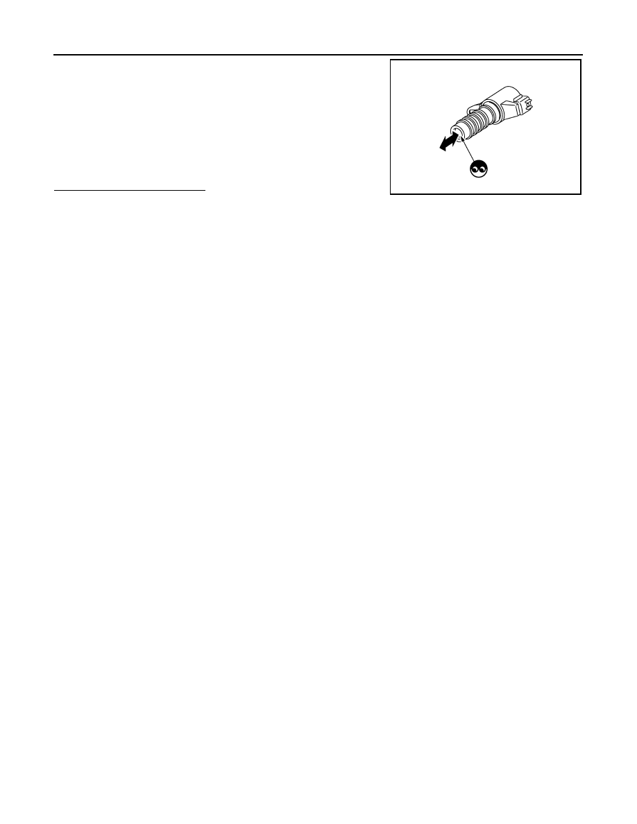
2.
Provide 12 V DC between intake valve timing control solenoid
valve terminals 1 and 2, and then interrupt it. Check that the
plunger moves as shown in the figure.
CAUTION:
Never apply 12 V DC continuously for 5 seconds or more.
Doing so may result in damage to the coil in intake valve
timing control solenoid valve.
NOTE:
Always replace O-ring when intake valve timing control
solenoid valve is removed.
Is the inspection result normal?
YES
>> INSPECTION END
NO
>> Replace malfunctioning intake valve timing control solenoid valve.
JMBIA0079ZZ
Нет комментариевНе стесняйтесь поделиться с нами вашим ценным мнением.
Текст