Infiniti FX35, FX50 (S51). Manual — part 804
P0014, P0024 EVT CONTROL
EC-757
< DTC/CIRCUIT DIAGNOSIS >
[VK50VE]
C
D
E
F
G
H
I
J
K
L
M
A
EC
N
P
O
CAUTION:
Always drive at a safe speed.
3.
Check 1st trip DTC.
With GST
Follow the procedure “With CONSULT-III” above.
Is 1st trip DTC detected?
YES
>> Go to
NO
>> INSPECTION END
Diagnosis Procedure
INFOID:0000000005237236
1.
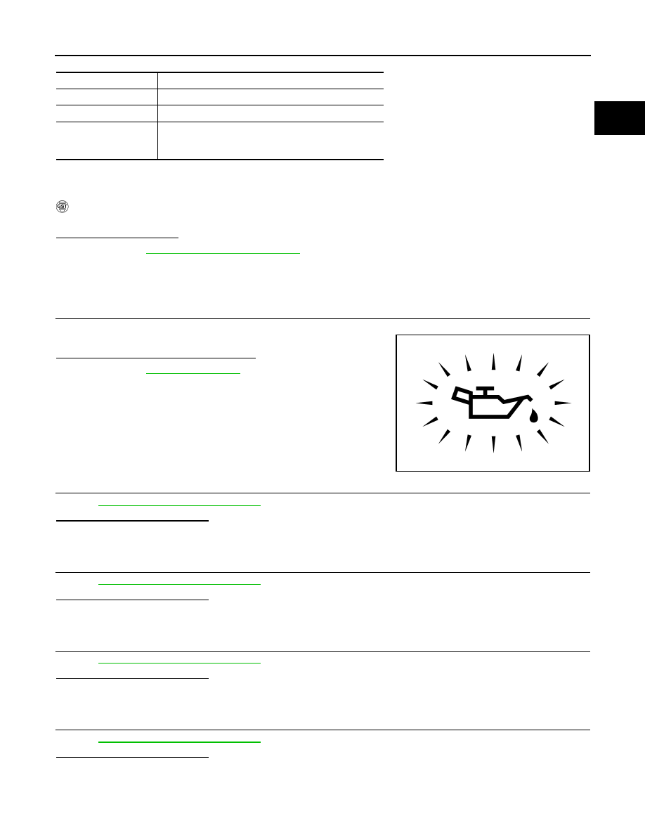
CHECK OIL PRESSURE WARNING LAMP
1.
Start engine.
2.
Check that oil pressure warning lamp is not illuminated.
Is oil pressure warning lamp illuminated?
YES
>> Go to
.
NO
>> GO TO 2.
2.
CHECK EXHAUST VALVE TIMING CONTROL SOLENOID VALVE
EC-758, "Component Inspection"
Is the inspection result normal?
YES
>> GO TO 3.
NO
>> Replace malfunctioning exhaust valve timing control solenoid valve.
3.
CHECK EXHAUST VALVE TIMING CONTROL POSITION SENSOR
EC-978, "Component Inspection"
Is the inspection result normal?
YES
>> GO TO 4.
NO
>> Replace malfunctioning exhaust valve timing control position sensor.
4.
CHECK CRANKSHAFT POSITION SENSOR
EC-876, "Component Inspection"
Is the inspection result normal?
YES
>> GO TO 5.
NO
>> Replace crankshaft position sensor.
5.
CHECK CAMSHAFT POSITION SENSOR
EC-881, "Component Inspection"
Is the inspection result normal?
YES
>> GO TO 6.
NO
>> Replace malfunctioning camshaft position sensor.
ENG SPEED
1,500 - 3,175 rpm (A constant rotation is maintained.)
COOLAN TEMP/S
More than 70
°
C (158
°
F)
Selector lever
1st or 2nd position
Driving location uphill
Driving vehicle uphill
(Increased engine load will help maintain the driving
conditions required for this test.)
PBIA8559J
EC-758
< DTC/CIRCUIT DIAGNOSIS >
[VK50VE]
P0014, P0024 EVT CONTROL
6.
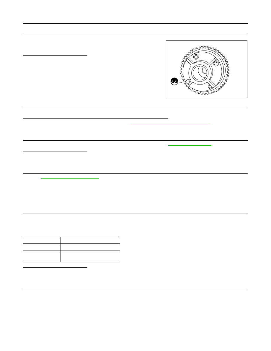
CHECK CAMSHAFT (EXH)
Check the following.
• Accumulation of debris to the signal plate of camshaft front end
• Chipping signal plate of camshaft front end
Is the inspection result normal?
YES
>> GO TO 7.
NO
>> Remove debris and clean the signal plate of camshaft
front end or replace camshaft.
7.
CHECK TIMING CHAIN INSTALLATION
Check service records for any recent repairs that may cause timing chain misaligned.
Are there any service records that may cause timing chain misaligned?
YES
>> Check timing chain installation. Refer to
EM-213, "Disassembly and Assembly"
.
NO
>> GO TO 8.
8.
CHECK LUBRICATION CIRCUIT
Perform “Inspection of Camshaft Sprocket (EXT) Oil Groove”. Refer to
Is the inspection result normal?
YES
>> GO TO 9.
NO
>> Clean lubrication line.
9.
CHECK INTERMITTENT INCIDENT
GI-36, "Intermittent Incident"
>> INSPECTION END
Component Inspection
INFOID:0000000005237237
1.
CHECK EXHAUST VALVE TIMING CONTROL SOLENOID VALVE-I
1.
Turn ignition switch OFF.
2.
Disconnect exhaust valve timing control solenoid valve harness connector.
3.
Check resistance between exhaust valve timing control solenoid valve terminals as per the following.
Is the inspection result normal?
YES
>> GO TO 2.
NO
>> Replace malfunctioning exhaust valve timing control solenoid valve.
2.
CHECK EXHAUST VALVE TIMING CONTROL SOLENOID VALVE-II
1.
Remove exhaust valve timing control solenoid valve.
JMBIA1571ZZ
Terminals
Resistance
1 and 2
7.0 - 7.7
Ω
[at 20
°
C (68
°
F)]
1 or 2 and ground
∞
Ω
(Continuity should not exist)
P0014, P0024 EVT CONTROL
EC-759
< DTC/CIRCUIT DIAGNOSIS >
[VK50VE]
C
D
E
F
G
H
I
J
K
L
M
A
EC
N
P
O
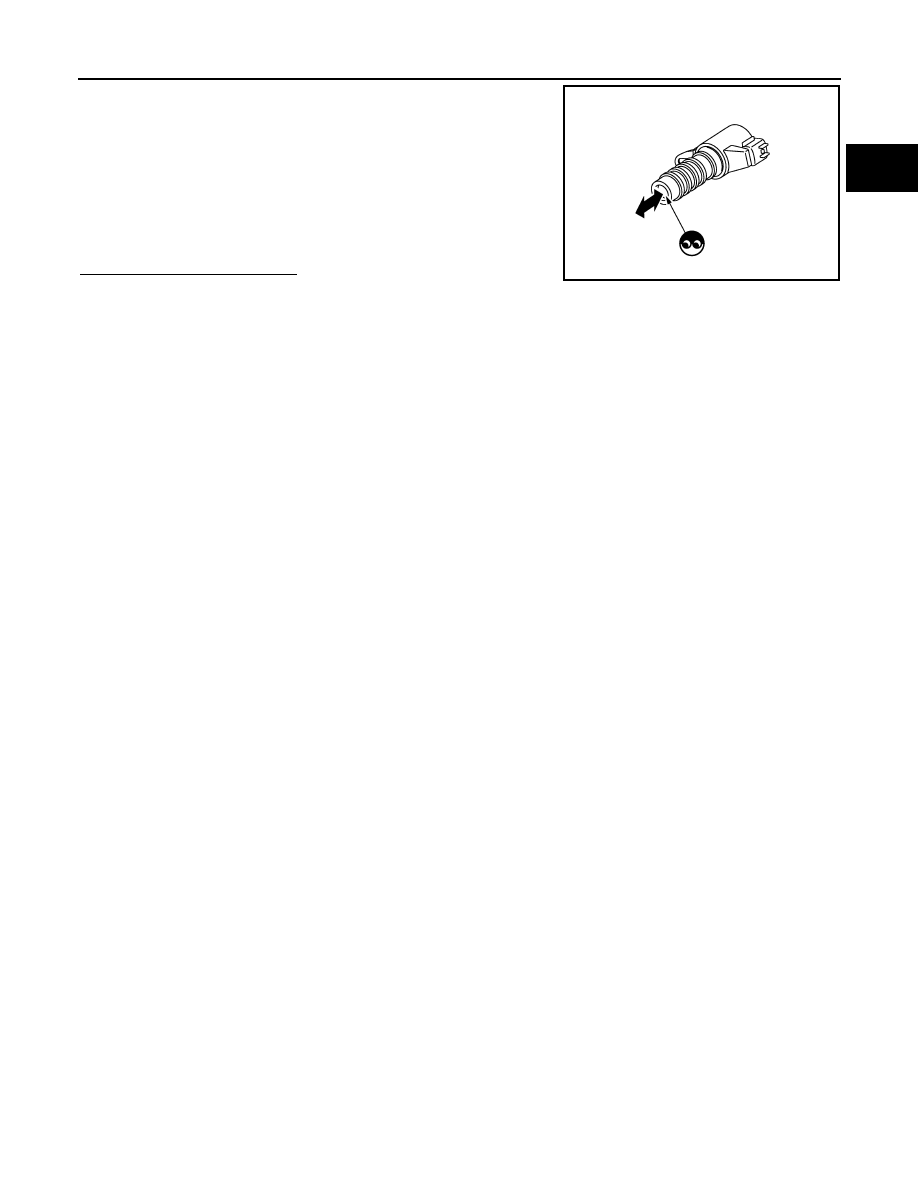
2.
Provide 12 V DC between exhaust valve timing control solenoid
valve terminals 1 and 2, and then interrupt it. Check that the
plunger moves as shown in the figure.
CAUTION:
Do not apply 12 V DC continuously for 5 seconds or more.
Doing so may result in damage to the coil in exhaust valve
timing control solenoid valve.
NOTE:
Always replace O-ring when exhaust valve timing control
solenoid valve is removed.
Is the inspection result normal?
YES
>> INSPECTION END
NO
>> Replace malfunctioning exhaust valve timing control solenoid valve.
JMBIA0079ZZ

EC-760
< DTC/CIRCUIT DIAGNOSIS >
[VK50VE]
P0031, P0032, P0051, P0052 A/F SENSOR 1 HEATER
P0031, P0032, P0051, P0052 A/F SENSOR 1 HEATER
Description
INFOID:0000000005237238
SYSTEM DESCRIPTION
The ECM performs ON/OFF duty control of the A/F sensor 1 heater corresponding to the engine operating
condition to keep the temperature of A/F sensor 1 element within the specified range.
DTC Logic
INFOID:0000000005237239
DTC DETECTION LOGIC
DTC CONFIRMATION PROCEDURE
1.
PRECONDITIONING
If DTC Confirmation Procedure has been previously conducted, always perform the following procedure
before conducting the next test.
1.
Turn ignition switch OFF and wait at least 10 seconds.
2.
Turn ignition switch ON.
3.
Turn ignition switch OFF and wait at least 10 seconds.
TESTING CONDITION:
Before performing the following procedure, confirm that battery voltage is more than 11 V at idle.
>> GO TO 2.
2.
PERFORM DTC CONFIRMATION PROCEDURE
1.
Start engine and let it idle for at least 10 seconds.
2.
Check 1st trip DTC.
Is 1st trip DTC detected?
YES
>> Go to
NG
>> INSPECTION END
Diagnosis Procedure
INFOID:0000000005237240
1.
CHECK GROUND CONNECTION
Sensor
Input signal to ECM
ECM function
Actuator
Camshaft position sensor
Crankshaft position sensor
Engine speed
Air fuel ratio (A/F) sensor 1
heater control
Air fuel ratio (A/F) sensor 1
heater
Mass air flow sensor
Amount of intake air
DTC No.
Trouble diagnosis name
DTC detecting condition
Possible cause
P0031
A/F sensor 1 heater (bank 1)
control circuit low
The current amperage in the A/F sensor 1 heater
circuit is out of the normal range.
(An excessively low voltage signal is sent to ECM
through the A/F sensor 1 heater.)
• Harness or connectors
(The A/F sensor 1 heater circuit is
open or shorted.)
• A/F sensor 1 heater
P0032
A/F sensor 1 heater (bank 1)
control circuit high
The current amperage in the A/F sensor 1 heater
circuit is out of the normal range.
(An excessively high voltage signal is sent to ECM
through the A/F sensor 1 heater.)
• Harness or connectors
(The A/F sensor 1 heater circuit is
shorted.)
• A/F sensor 1 heater
P0051
A/F sensor 1 heater (bank 2)
control circuit low
The current amperage in the A/F sensor 1 heater
circuit is out of the normal range.
(An excessively low voltage signal is sent to ECM
through the A/F sensor 1 heater.)
• Harness or connectors
(The A/F sensor 1 heater circuit is
open or shorted.)
• A/F sensor 1 heater
P0052
A/F sensor 1 heater (bank 2)
control circuit high
The current amperage in the A/F sensor 1 heater
circuit is out of the normal range.
(An excessively high voltage signal is sent to ECM
through the A/F sensor 1 heater.)
• Harness or connectors
(The A/F sensor 1 heater circuit is
shorted.)
• A/F sensor 1 heater
Нет комментариевНе стесняйтесь поделиться с нами вашим ценным мнением.
Текст