Infiniti FX35, FX50 (S51). Manual — part 614
DRIVE PINION
DLN-291
< UNIT DISASSEMBLY AND ASSEMBLY >
[REAR FINAL DRIVE: R230]
C
E
F
G
H
I
J
K
L
M
A
B
DLN
N
O
P
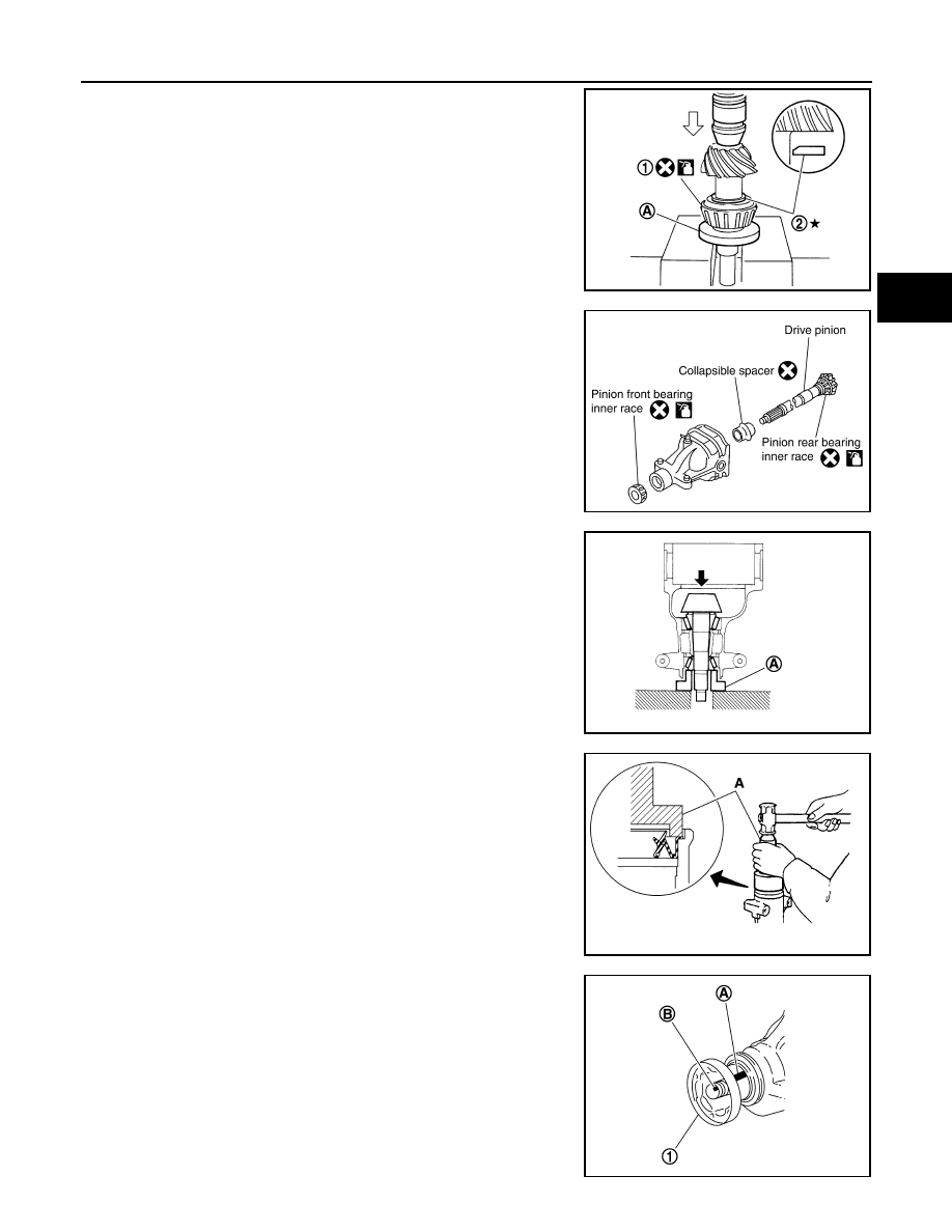
3.
Install selected drive pinion height adjusting washer (2) to drive
pinion. Press pinion rear bearing inner race (1) to it, using drift
(A) [SST: ST30022000 (
—
)].
CAUTION:
• Be careful of the direction of pinion height adjusting
washer. (Assemble as shown in the figure.)
• Never reuse pinion rear bearing inner race.
4.
Assemble collapsible spacer to drive pinion.
CAUTION:
Never reuse collapsible spacer.
5.
Apply gear oil to pinion rear bearing, and assemble drive pinion
into gear carrier.
6.
Apply gear oil to pinion front bearing, and assemble pinion front
bearing inner race to drive pinion assembly.
CAUTION:
Never reuse pinion front bearing inner race.
7.
Using suitable spacer (A), press the pinion front bearing inner
race to drive pinion as far as drive pinion nut can be tightened.
8.
Using the drift (A) [SST: ST15310000 (
—
)], install front oil
seal in evenly until it becomes flush with the gear carrier.
CAUTION:
• Never reuse oil seal.
• When installing, never incline oil seal.
• Apply multi-purpose grease onto oil seal lips, and gear oil
onto the circumference of oil seal.
9.
Install companion flange (1).
NOTE:
When reusing drive pinion, align the matching mark (B) of drive
pinion with the matching mark (A) of companion flange, and then
install companion flange.
PDIA0805J
PDIA0492E
PDIA0762J
PDIA0764J
PDIA0750J
DLN-292
< UNIT DISASSEMBLY AND ASSEMBLY >
[REAR FINAL DRIVE: R230]
DRIVE PINION
10. Apply anti-corrosion oil to the thread and seat of drive pinion
lock nut, and temporarily tighten drive pinion lock nut to drive
pinion.
CAUTION:
Never reuse drive pinion lock nut.
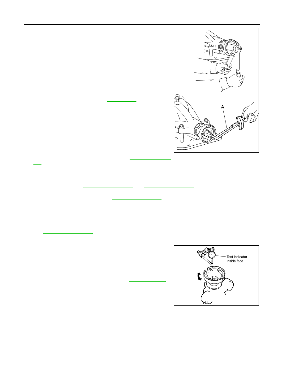
11. Adjust to the drive pinion lock nut tightening torque and pinion
bearing preload torque.
CAUTION:
• Adjust to the lower limit of the drive pinion lock nut tight-
ening torque first.
• If the preload torque exceeds the specified value, replace
collapsible spacer and tighten it again to adjust. Never
loosen drive pinion lock nut to adjust the preload torque.
• After adjustment, rotate drive pinion back and forth 2 to 3
times to check for unusual noise, rotation malfunction,
and other malfunctions.
12. Install differential case assembly. Refer to
CAUTION:
Never install rear cover at this timing.
13. Check and adjust drive gear runout, tooth contact, drive gear to drive pinion backlash, and companion
flange runout. Refer to
Recheck above items. Readjust the above description, if necessary.
14. Check total preload torque. Refer to
.
15. Install rear cover. Refer to
Adjustment
INFOID:0000000005249286
TOOTH CONTACT
COMPANION FLANGE RUNOUT
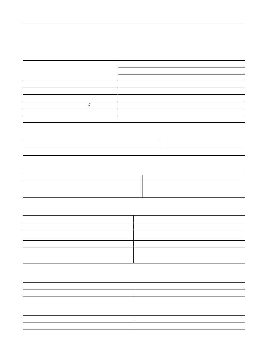
1.
Fit a test indicator to the inner side of companion flange (socket
diameter).
2.
Rotate companion flange to check for runout.
3.
If the runout value is outside the runout limit, follow the proce-
dure below to adjust.
a.
Check for runout while changing the phase between companion
flange and drive pinion by 90
°
step, and search for the position where the runout is the minimum.
b.
If the runout value is still outside of the limit after the phase has been changed, possible cause will be an
assembly malfunction of drive pinion and pinion bearing and malfunction of pinion bearing. Check for
these items and repair if necessary.
c.
If the runout value is still outside of the limit after the check and repair, replace companion flange.
A
: Preload gauge [SST: ST3127S000 (J-25765-A)]
Standard
Pinion bearing preload
: Refer to
PDIA0765J
Limit
Companion flange runout
: Refer to
.
PDIA0490E
DRIVE PINION
DLN-293
< UNIT DISASSEMBLY AND ASSEMBLY >
[REAR FINAL DRIVE: R230]
C
E
F
G
H
I
J
K
L
M
A
B
DLN
N
O
P
Inspection After Disassembly
INFOID:0000000005249287
DRIVE GEAR AND DRIVE PINION
• Clean up the disassembled parts.
• If the gear teeth never mesh or line-up correctly, determine the cause and adjust or replace as necessary.
• If the gears are worn, cracked, damaged, pitted or chipped (by friction) noticeably, replace with new drive
gear and drive pinion as a set.
BEARING
• Clean up the disassembled parts.
• If any chipped (by friction), pitted, worn, rusted or scratched marks, or unusual noise from the bearing is
observed, replace as a bearing assembly (as a new set).
SIDE GEAR AND PINION MATE GEAR
• Clean up the disassembled parts.
• If any cracks or damage on the surface of the tooth is found, replace.
• If any worn or chipped mark on the contact sides of the thrust washer is found, replace.
SIDE GEAR THRUST WASHER AND PINION MATE THRUST WASHER
• Clean up the disassembled parts.
• If it is chipped (by friction), damaged, or unusually worn, replace.
OIL SEAL
• Whenever disassembled, replace.
• If wear, deterioration of adherence (sealing force lips), or damage is detected on the lips, replace them.
DIFFERENTIAL CASE
• Clean up the disassembled parts.
• If any wear or crack on the contact sides of the differential case is found, replace.
COMPANION FLANGE
• Clean up the disassembled parts.
• If any chipped mark [about 0.1 mm, (0.004 in)] or other damage on the contact sides of the lips of the com-
panion flange is found, replace.
DLN-294
< SERVICE DATA AND SPECIFICATIONS (SDS)
[REAR FINAL DRIVE: R230]
SERVICE DATA AND SPECIFICATIONS (SDS)
SERVICE DATA AND SPECIFICATIONS (SDS)
SERVICE DATA AND SPECIFICATIONS (SDS)
General Specification
INFOID:0000000005249288
Drive Gear Runout
INFOID:0000000005249289
Unit: mm (in)
Side Gear Clearance
INFOID:0000000005249290
Unit: mm (in)
Preload Torque
INFOID:0000000005249291
Backlash
INFOID:0000000005249292
Unit: mm (in)
Companion Flange Runout
INFOID:0000000005249293
Unit: mm (in)
Applied model
AWD
VK50VE
A/T
Final drive model
R230
Gear ratio
3.538
Number of teeth (Drive gear/Drive pinion)
46 / 13
Oil capacity (Approx.)
(US pt, lmp pt)
1.75 (3 3/4, 3 1/8)
Number of pinion gears
2
Drive pinion adjustment spacer type
Collapsible
Item
Runout limit
Drive gear back face
0.05 (0.0020) or less
Item
Specification
Side gear back clearance
(Clearance limit between side gear and differential case for adjusting
side gear backlash)
0.20 (0.0079) or less
(Each gear should rotate smoothly without excessive resis-
tance during differential motion.)
Item
Specification
Drive pinion bearing preload torque
1.76
−
2.65 N·m (0.18
−
0.27 kg
−
m, 16
−
23 in-lb)
Side bearing preload torque (reference value determined by drive
gear bolt pulling force)
0.29
−
1.47 N·m (0.03
−
0.14 kg
−
m, 3
−
13 in-lb)
Drive gear bolt pulling force (by spring gauge)
34.2
−
39.2 N (3.5
−
3.9 kg, 7.7
−
8.8 lb)
Total preload torque
(Total preload torque = drive pinion bearing preload torque + Side
bearing preload torque)
2.06
−
4.12 N·m (0.21
−
0.42 kg
−
m, 19
−
36 in-lb)
Item
Specification
Drive gear to drive pinion gear
0.13
−
0.18 (0.0051
−
0.0070)
Item
Runout limit
Outer side of the companion flange
0.08 (0.0031) or less
Нет комментариевНе стесняйтесь поделиться с нами вашим ценным мнением.
Текст