Infiniti FX35, FX50 (S51). Manual — part 203
AV
SIDE CAMERA LH
AV-585
< REMOVAL AND INSTALLATION >
[NAVIGATION (TWIN MONITOR)]
C
D
E
F
G
H
I
J
K
L
M
B
A
O
P
SIDE CAMERA LH
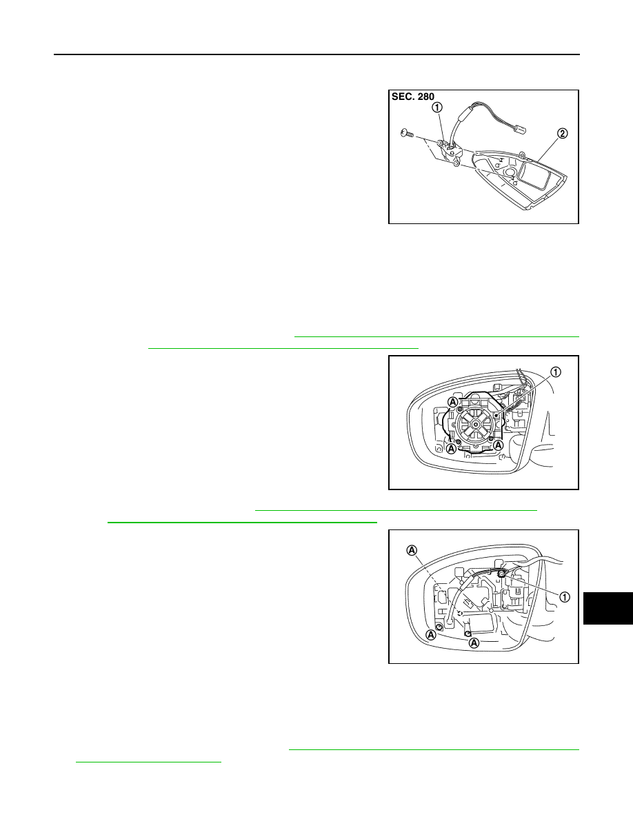
Exploded View
INFOID:0000000005475043
Removal and Installation
INFOID:0000000005475044
REMOVAL
1.
Remove glass mirror (driver side). Refer to
MIR-100, "DOOR MIRROR ASSEMBLY : Exploded View"
MIR-78, "DOOR MIRROR ASSEMBLY : Exploded View"
(with ADP).
2.
Remove screws (A), and actuator connector, and then actuator
(1).
3.
Remove door mirror cover. Refer to
MIR-100, "DOOR MIRROR ASSEMBLY : Exploded View"
MIR-78, "DOOR MIRROR ASSEMBLY : Exploded View"
(with ADP).
4.
Remove screws (A) and connector (1), and then remove side
camera finisher assembly (LH).
5.
Remove side camera (LH) mounting screws
6.
Remove side camera (LH).
INSTALLATION
1.
Installation is the reverse order of removal.
2.
Perform camera image calibration. Refer to
AV-462, "CALIBRATING CAMERA IMAGE (AROUND VIEW
CAUTION:
JPNIA0900ZZ
1.
Side camera (LH)
2.
Side camera finisher assembly
JSNIA1471ZZ
JSNIA1472ZZ
AV-586
< REMOVAL AND INSTALLATION >
[NAVIGATION (TWIN MONITOR)]
SIDE CAMERA LH
Perform the calibration and perform the writing to the around view monitor control unit when remov-
ing and replacing each camera, removing the camera mounting parts (front grille, door mirror, etc.)
and replacing the around view monitor control unit.
AV
SIDE CAMERA RH
AV-587
< REMOVAL AND INSTALLATION >
[NAVIGATION (TWIN MONITOR)]
C
D
E
F
G
H
I
J
K
L
M
B
A
O
P
SIDE CAMERA RH
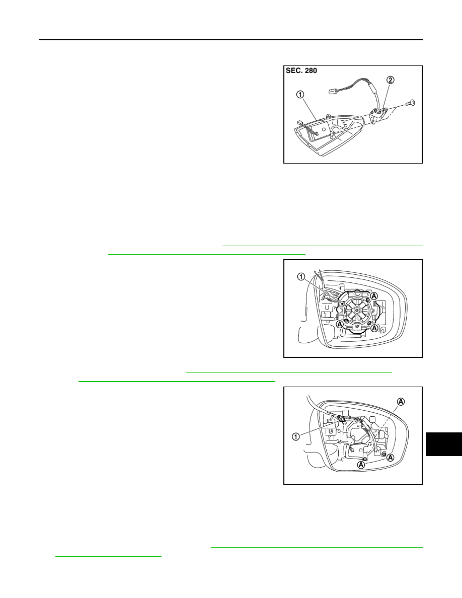
Exploded View
INFOID:0000000005475047
Removal and Installation
INFOID:0000000005475048
REMOVAL
1.
Remove glass mirror (passenger side). Refer to
MIR-100, "DOOR MIRROR ASSEMBLY : Exploded View"
MIR-78, "DOOR MIRROR ASSEMBLY : Exploded View"
(with ADP).
2.
Remove screws (A) and actuator connector, and then actuator
(1).
3.
Remove door mirror cover. Refer to
MIR-100, "DOOR MIRROR ASSEMBLY : Exploded View"
MIR-78, "DOOR MIRROR ASSEMBLY : Exploded View"
(with ADP).
4.
Remove screws (A) and connector (1), and then remove side
camera finisher assembly (RH).
5.
Remove side camera (RH) screws.
6.
Remove side camera (RH).
INSTALLATION
1.
Installation is the reverse order of removal.
2.
Perform camera image calibration. Refer to
AV-462, "CALIBRATING CAMERA IMAGE (AROUND VIEW
CAUTION:
JPNIA0902ZZ
1.
Side camera finisher assembly
2.
Side camera (RH)
JSNIA1473ZZ
JSNIA1474ZZ
AV-588
< REMOVAL AND INSTALLATION >
[NAVIGATION (TWIN MONITOR)]
SIDE CAMERA RH
Perform the calibration and perform the writing to the around view monitor control unit when remov-
ing and replacing each camera, removing the camera mounting parts (front grille, door mirror, etc.)
and replacing the around view monitor control unit.
Нет комментариевНе стесняйтесь поделиться с нами вашим ценным мнением.
Текст