Infiniti FX35, FX50 (S51). Manual — part 202
AV
GPS ANTENNA
AV-581
< REMOVAL AND INSTALLATION >
[NAVIGATION (TWIN MONITOR)]
C
D
E
F
G
H
I
J
K
L
M
B
A
O
P
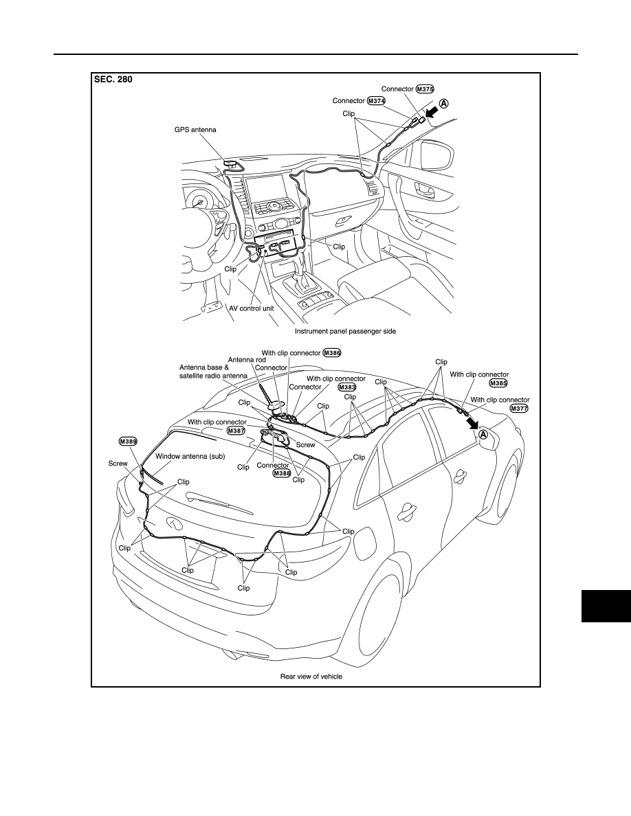
Feeder Layout
INFOID:0000000005475036
JSNIA1468GB
AV-582
< REMOVAL AND INSTALLATION >
[NAVIGATION (TWIN MONITOR)]
AROUND VIEW MONITOR CONTROL UNIT
AROUND VIEW MONITOR CONTROL UNIT
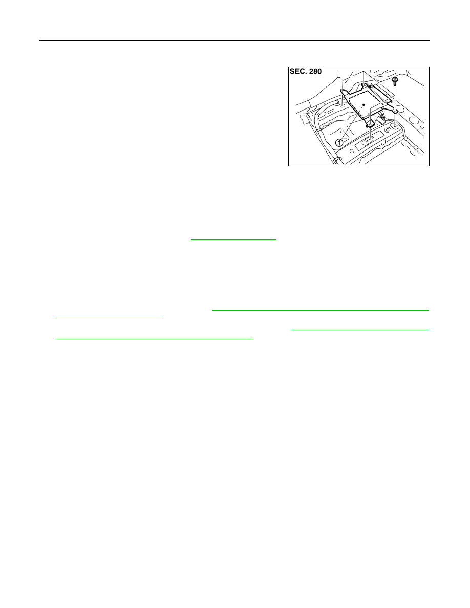
Exploded View
INFOID:0000000005475037
Removal and Installation
INFOID:0000000005475038
REMOVAL
1.
Remove front seat (LH side). Refer to
.
2.
Remove floor carpet. Keep a service area.
3.
Remove around view monitor control unit mounting screws.
4.
Disconnect connector and remove around view monitor control unit.
INSTALLATION
1.
Installation is the reverse order of removal.
2.
Perform camera image calibration. Refer to
AV-462, "CALIBRATING CAMERA IMAGE (AROUND VIEW
3.
Perform predictive course line center position adjustment. Refer to
AV-462, "PREDICTIVE COURSE LINE
CENTER POSITION ADJUSTMENT : Work Procedure"
CAUTION:
Perform the calibration and perform the writing to the around view monitor control unit when remov-
ing and replacing each camera, removing the camera mounting parts (front grille, door mirror, etc.)
and replacing the around view monitor control unit.
JPNIA0898ZZ
1.
Around view monitor control unit
AV
FRONT CAMERA
AV-583
< REMOVAL AND INSTALLATION >
[NAVIGATION (TWIN MONITOR)]
C
D
E
F
G
H
I
J
K
L
M
B
A
O
P
FRONT CAMERA
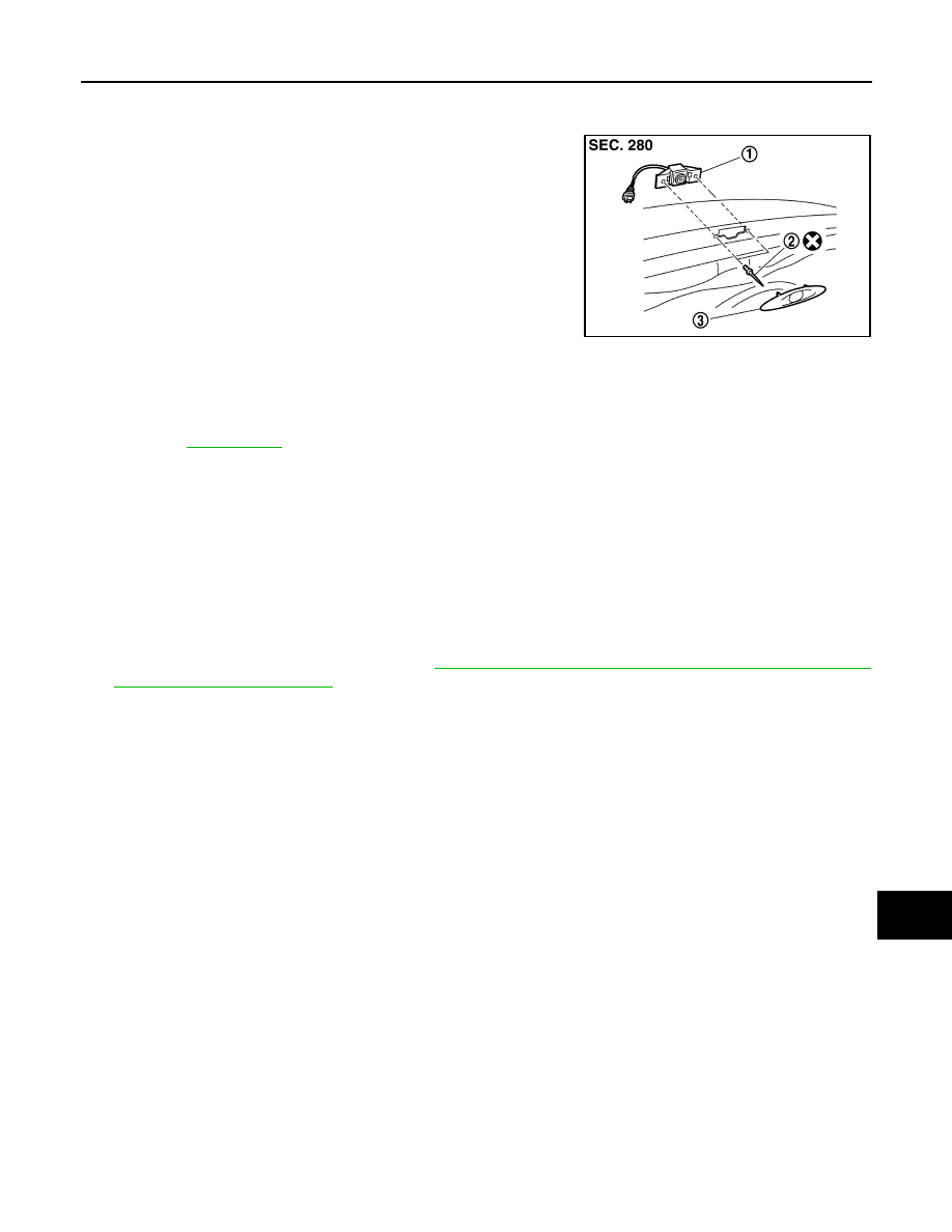
Exploded View
INFOID:0000000005475039
Removal and Installation
INFOID:0000000005475040
REMOVAL
1.
Remove front camera finisher.
2.
Remove front camera mounting rivet.
3.
Remove front camera.
INSTALLATION
1.
Installation is the reverse order of removal.
2.
Perform camera image calibration. Refer to
AV-462, "CALIBRATING CAMERA IMAGE (AROUND VIEW
CAUTION:
Perform the calibration and perform the writing to the around view monitor control unit when remov-
ing and replacing each camera, removing the camera mounting parts (front grille, door mirror, etc.)
and replacing the around view monitor control unit.
JSNIA1469ZZ
1.
Front camera
2.
Rivet
3.
Front camera finisher
for symbols in the figure.
AV-584
< REMOVAL AND INSTALLATION >
[NAVIGATION (TWIN MONITOR)]
REAR CAMERA
REAR CAMERA
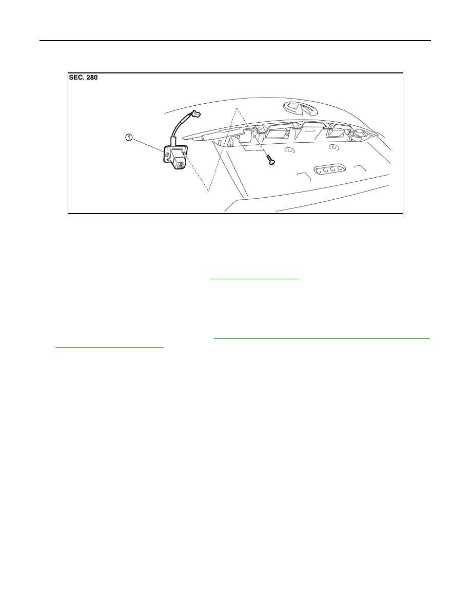
Exploded View
INFOID:0000000005475041
Removal and Installation
INFOID:0000000005475042
REMOVAL
1.
Remove door handle cover upper. Refer to
2.
Remove rear camera mounting screws and rear camera harness connector.
3.
Remove rear camera.
INSTALLATION
1.
Installation is the reverse order of removal.
2.
Perform camera image calibration. Refer to
AV-462, "CALIBRATING CAMERA IMAGE (AROUND VIEW
CAUTION:
Perform the calibration and perform the writing to the around view monitor control unit when remov-
ing and replacing each camera, removing the camera mounting parts (front grille, door mirror, etc.)
and replacing the around view monitor control unit.
JSNIA1470ZZ
1.
Rear camera
Нет комментариевНе стесняйтесь поделиться с нами вашим ценным мнением.
Текст