Infiniti FX35, FX50 (S51). Manual — part 1752
PRECAUTIONS
SRC-173
< PRECAUTION >
C
D
E
F
G
I
J
K
L
M
A
B
SRC
N
O
P
PRECAUTION
PRECAUTIONS
Precaution for Supplemental Restraint System (SRS) "AIR BAG" and "SEAT BELT
PRE-TENSIONER"
INFOID:0000000005241266
The Supplemental Restraint System such as “AIR BAG” and “SEAT BELT PRE-TENSIONER”, used along
with a front seat belt, helps to reduce the risk or severity of injury to the driver and front passenger for certain
types of collision. This system includes seat belt switch inputs and dual stage front air bag modules. The SRS
system uses the seat belt switches to determine the front air bag deployment, and may only deploy one front
air bag, depending on the severity of a collision and whether the front occupants are belted or unbelted.
Information necessary to service the system safely is included in the “SRS AIR BAG” and “SEAT BELT” of this
Service Manual.
WARNING:
• To avoid rendering the SRS inoperative, which could increase the risk of personal injury or death in
the event of a collision which would result in air bag inflation, all maintenance must be performed by
an authorized NISSAN/INFINITI dealer.
• Improper maintenance, including incorrect removal and installation of the SRS, can lead to personal
injury caused by unintentional activation of the system. For removal of Spiral Cable and Air Bag
Module, see the “SRS AIR BAG”.
• Do not use electrical test equipment on any circuit related to the SRS unless instructed to in this
Service Manual. SRS wiring harnesses can be identified by yellow and/or orange harnesses or har-
ness connectors.
PRECAUTIONS WHEN USING POWER TOOLS (AIR OR ELECTRIC) AND HAMMERS
WARNING:
• When working near the Air Bag Diagnosis Sensor Unit or other Air Bag System sensors with the
ignition ON or engine running, DO NOT use air or electric power tools or strike near the sensor(s)
with a hammer. Heavy vibration could activate the sensor(s) and deploy the air bag(s), possibly
causing serious injury.
• When using air or electric power tools or hammers, always switch the ignition OFF, disconnect the
battery, and wait at least 3 minutes before performing any service.
Service
INFOID:0000000005241267
• Do not use electrical test equipment to check SRS circuits unless instructed to in this Service Manual.
• Before servicing the SRS, turn ignition switch OFF, disconnect battery negative terminal and wait at least 3
minutes.
For approximately 3 minutes after the battery negative terminal is removed, it is still possible for the air bag
and seat belt pre-tensioner to deploy. Therefore, do not work on any SRS connectors or wires until at least 3
minutes have elapsed.
• Diagnosis sensor unit must always be installed with their arrow marks “
⇐
” pointing towards the front of the
vehicle for proper operation. Also check diagnosis sensor unit for cracks, deformities, or rust before installa-
tion and replace if necessary.
• The spiral cable must be aligned in the neutral position since its rotations are limited. Do not turn steering
wheel and column after removal of steering gear.
• Handle air bag module carefully. Always place driver and front passenger air bag modules with the pad side
facing upward and seat mounted front side air bag module standing with the stud bolt side facing down.
• Perform self-diagnosis to check entire SRS for proper function after replacing any components.
• After air bag inflates, the front instrument panel assembly must be replaced if damaged.
• Always replace instrument panel pad following front passenger air bag deployment.
Occupant Detection System Precaution
INFOID:0000000005241268
• Replace Occupant Detection System control unit and passenger front seat cushion as an assembly.
SE-84, "Removal and Installation"
.
ST-1
STEERING
C
D
E
F
H
I
J
K
L
M
SECTION
ST
A
B
ST
N
O
P
CONTENTS
STEERING SYSTEM
SYMPTOM DIAGNOSIS . . . . . . . ...
NOISE, VIBRATION AND HARSHNESS
(NVH) TROUBLESHOOTING . . . . . . . .
NVH Troubleshooting Chart . . . . . . . . . ..
PRECAUTION . . . . . . . . . . . ...
PRECAUTIONS . . . . . . . . . . . . ...
Precaution Necessary for Steering Wheel Rota-
tion after Battery Disconnect . . . . . . . . .....
Service Notice or Precautions for Steering System
. ..
PREPARATION . . . . . . . . . . .
PREPARATION . . . . . . . . . . . . ...
Special Service Tools . . . . . . . . . . . ....
Commercial Service Tools . . . . . . . . . ..
PERIODIC MAINTENANCE . . . . . . .
POWER STEERING FLUID . . . . . . . ...
Inspection . . . . . . . . . . . . . . . .
STEERING WHEEL . . . . . . . . . . .
Inspection . . . . . . . . . . . . . . . .
REMOVAL AND INSTALLATION . . . ...
STEERING WHEEL . . . . . . . . . . .
Exploded View . . . . . . . . . . . . . .
Removal and Installation . . . . . . . . . . .
STEERING COLUMN . . . . . . . . . . .
WITHOUT ELECTRIC MOTOR . . . . . . . . .
WITHOUT ELECTRIC MOTOR : Exploded View .
WITHOUT ELECTRIC MOTOR : Removal and In-
stallation . . . . . . . . . . . . . . . . ..
WITHOUT ELECTRIC MOTOR : Inspection . . ...
WITH ELECTRIC MOTOR . . . . . . . . . . .
WITH ELECTRIC MOTOR : Exploded View . . ...
WITH ELECTRIC MOTOR : Removal and Instal-
lation . . . . . . . . . . . . . . . . . .
WITH ELECTRIC MOTOR : Inspection . . . . ...
LOWER SHAFT . . . . . . . . . . . .
Exploded View . . . . . . . . . . . . . . .
Removal and Installation . . . . . . . . . . .
Inspection . . . . . . . . . . . . . . . .
STEERING GEAR AND LINKAGE . . . . ...
Exploded View . . . . . . . . . . . . . . .
Removal and Installation . . . . . . . . . . .
Disassembly and Assembly . . . . . . . . . .
Inspection . . . . . . . . . . . . . . . .
POWER STEERING OIL PUMP . . . . . ...
VQ35HR . . . . . . . . . . . . . . . . . .
VQ35HR : Exploded View . . . . . . . . . ...
VQ35HR : Removal and Installation . . . . . .
VQ35HR : Disassembly and Assembly . . . . ...
VQ35HR : Inspection . . . . . . . . . . . ...
VK50VE . . . . . . . . . . . . . . . . . ..
VK50VE : Exploded View . . . . . . . . . .
VK50VE : Removal and Installation . . . . . . .
VK50VE : Disassembly and Assembly . . . . .
VK50VE : Inspection . . . . . . . . . . . .
HYDRAULIC LINE . . . . . . . . . . .
VQ35HR . . . . . . . . . . . . . . . . . .
VQ35HR : Exploded View . . . . . . . . . ...
VK50VE . . . . . . . . . . . . . . . . . ..
VK50VE : Exploded View . . . . . . . . . .
SERVICE DATA AND SPECIFICATIONS
(SDS) . . . . . . . . . . . . . . .
ST-2
SERVICE DATA AND SPECIFICATIONS
(SDS) . . . . . . . . . . . . . . . . ..
General Specifications . . . . . . . . . . ....
Steering Wheel Axial End Play and Play . . . ....
Steering Wheel Turning Force . . . . . . . ....
Steering Angle . . . . . . . . . . . . . ....
Steering Column Length . . . . . . . . . . .
Steering Column Mounting Dimensions . . . . .
Steering Column Operating Range . . . . . . .
Lower Shaft Sliding Range . . . . . . . . . .
Rack Sliding Force . . . . . . . . . . . . ..
Rack Stroke . . . . . . . . . . . . . . .
Socket Swing Force and Rotating Torque . . . ..
Socket Axial End Play . . . . . . . . . . . .
Inner Socket Length . . . . . . . . . . . .
NOISE, VIBRATION AND HARSHNESS (NVH) TROUBLESHOOTING
ST-3
< SYMPTOM DIAGNOSIS >
C
D
E
F
H
I
J
K
L
M
A
B
ST
N
O
P
SYMPTOM DIAGNOSIS
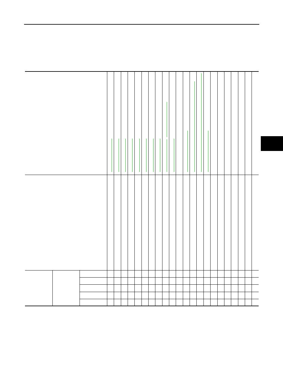
NOISE, VIBRATION AND HARSHNESS (NVH) TROUBLESHOOTING
NVH Troubleshooting Chart
INFOID:0000000005235263
2WD MODELS (WITHOUT ELECTRIC MOTOR)
Use the chart below to find the cause of the symptom. If necessary, repair or replace these parts.
×
: Applicable
2WD MODELS (WITH ELECTRIC MOTOR)
Reference
,
—
NV
H
in
D
L
N
s
e
c
ti
on.
NV
H
in
D
L
N
s
e
c
ti
on.
NV
H
in
F
A
X
, R
A
X
,
FS
U
, R
S
U
se
ct
ion
.
NV
H in
WT se
cti
on
.
NV
H in
WT se
cti
on
.
NV
H
in
R
A
X
s
e
c
tio
n.
NV
H
in
B
R
s
ec
tio
n.
Possible cause and SUSPECTED PARTS
F
lui
d l
ev
el
Ai
r i
n
hy
dra
u
lic sy
st
em
Ou
ter/
inn
e
r
so
ck
et
ba
ll
joi
n
t swi
n
g
ing
to
rqu
e
Ou
ter/
inn
e
r
so
ck
et
ba
ll
joi
n
t rot
a
ti
ng
tor
que
Ou
ter/
inn
e
r
so
ck
et
ba
ll
joi
n
t en
d p
la
y
S
te
eri
ng
fl
ui
d
l
e
ak
ag
e
S
te
e
ri
ng
whe
e
l pl
ay
S
te
e
ri
ng
ge
ar rac
k sl
id
in
g
fo
rce
Dri
v
e
be
lt
lo
os
en
es
s
Im
pro
p
e
r st
ee
ri
ng
wh
ee
l
Im
p
rop
er i
n
s
tal
la
tio
n
o
r lo
os
en
es
s
of
til
t l
o
c
k
l
e
v
e
r
M
ou
nt
ing
lo
os
e
nes
s
S
tee
rin
g
c
o
lum
n
de
form
at
ion
o
r da
ma
ge
Im
p
rop
er i
n
s
tal
la
tio
n
o
r lo
os
en
es
s
of
st
ee
ring
c
o
lu
m
n
S
te
e
ri
ng
li
nk
ag
e l
o
o
se
n
e
ss
P
R
OPE
LLE
R SHAFT
DIFFERENTIAL
A
XLE and
SUSP
ENSION
TI
RE
ROAD W
H
EEL
DRIV
E SHAFT
BR
AK
E
Symptom
Steering
Noise
× × × × × × × × ×
× ×
× × × × × × ×
Shake
×
×
×
× × × × ×
Vibration
×
× × ×
×
× ×
×
Shimmy
×
×
×
× × ×
×
Judder
×
×
× × ×
×
Нет комментариевНе стесняйтесь поделиться с нами вашим ценным мнением.
Текст