Infiniti FX35, FX50 (S51). Manual — part 1753
ST-4
< SYMPTOM DIAGNOSIS >
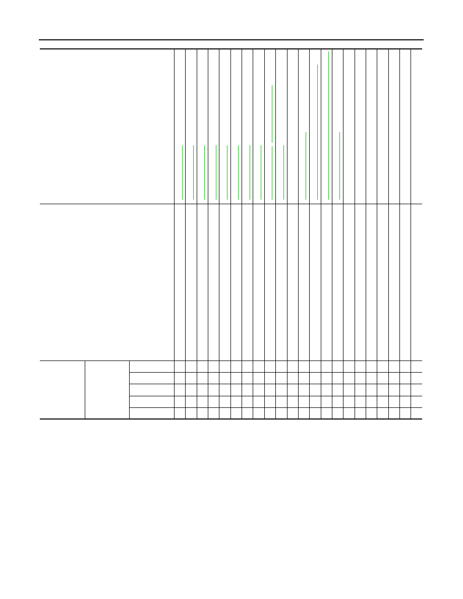
NOISE, VIBRATION AND HARSHNESS (NVH) TROUBLESHOOTING
Use the chart below to find the cause of the symptom. If necessary, repair or replace these parts.
×
: Applicable
AWD MODELS (WITHOUT ELECTRIC MOTOR)
Reference
,
—
NVH in DLN section.
NVH in DLN section.
NVH in F
A
X, RAX, FSU,
RSU section.
NVH in WT
section.
NVH in WT
section.
NVH in RAX
section.
NVH in BR section.
Possible cause and SUSPECTED PARTS
Flu
id leve
l
Ai
r in
hy
dra
u
lic
sy
st
em
Ou
te
r/in
ne
r so
ck
e
t ba
ll jo
int
s
w
in
g
in
g
t
o
rqu
e
Ou
te
r/in
ne
r so
cke
t ba
ll jo
int
rot
a
ti
ng
to
rqu
e
Ou
te
r/in
ne
r so
ck
e
t ba
ll jo
int
en
d
pla
y
S
tee
ri
ng
f
lui
d
le
a
ka
g
e
S
tee
ri
ng
wh
ee
l p
lay
S
te
e
rin
g
ge
ar ra
ck
s
lid
in
g f
o
rc
e
Dri
v
e
b
elt
lo
os
en
es
s
Imp
rop
er ste
e
ri
ng
whe
e
l
Im
pro
pe
r
in
st
al
lat
ion
o
r lo
os
en
es
s o
f t
ilt
lo
ck
l
e
ve
r
M
ou
nt
ing
lo
os
en
es
s
S
tee
ri
ng
c
o
lu
m
n
d
e
fo
rm
at
io
n
or da
ma
ge
Im
pro
pe
r
in
st
al
lat
ion
o
r lo
os
en
es
s o
f st
e
eri
ng
co
lu
mn
S
te
erin
g lin
ka
ge
lo
os
en
es
s
PROP
ELLER SHAFT
D
IFFERENTIAL
AXLE and
S
U
S
PENSION
TIRE
R
O
AD WHEEL
D
R
IVE SHAF
T
BRAKE
Symptom
Steering
Noise
× × × × × × × × ×
× ×
× × × × × × ×
Shake
×
×
×
× × × × ×
Vibration
×
× × ×
×
× ×
×
Shimmy
×
×
×
× × ×
×
Judder
×
×
× × ×
×

NOISE, VIBRATION AND HARSHNESS (NVH) TROUBLESHOOTING
ST-5
< SYMPTOM DIAGNOSIS >
C
D
E
F
H
I
J
K
L
M
A
B
ST
N
O
P
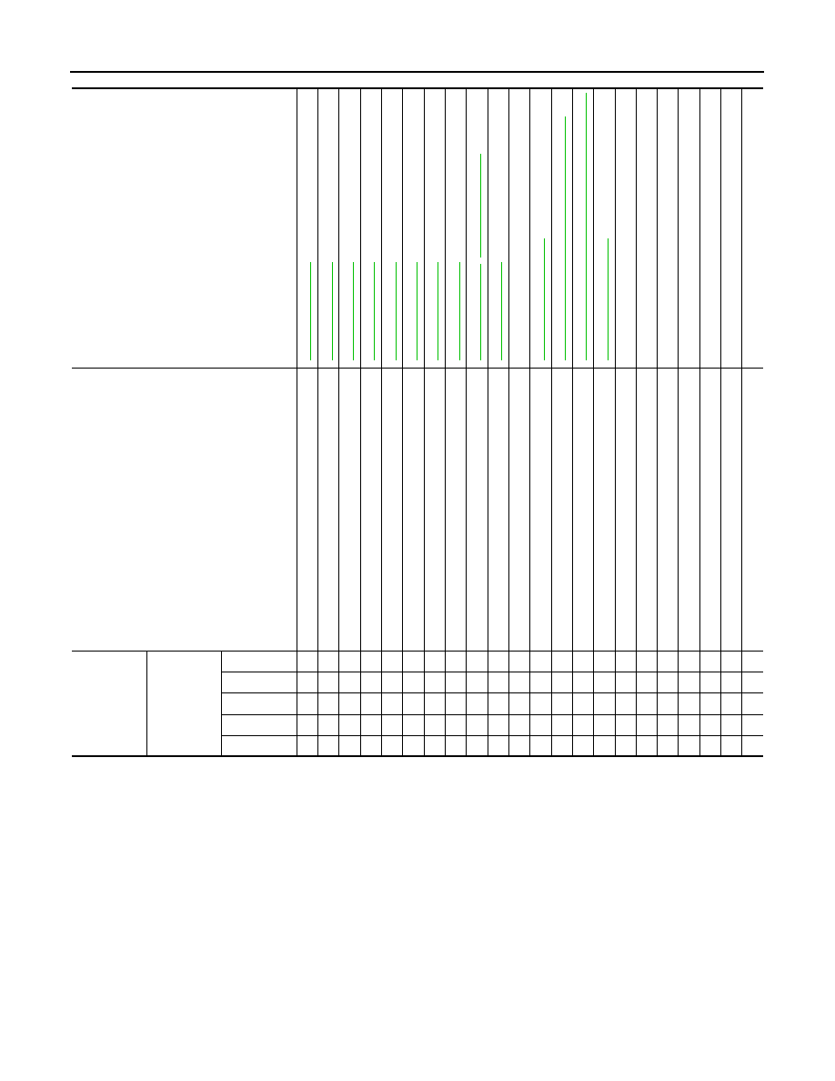
Use the chart below to find the cause of the symptom. If necessary, repair or replace these parts.
×
: Applicable
AWD MODELS (WITH ELECTRIC MOTOR)
Reference
,
—
NVH in DLN section.
NVH in DLN section.
NVH in F
A
X, RAX,
FSU, RSU
section.
NVH in WT
section.
NVH in WT
section.
NVH in F
A
X, RAX
section.
NVH in BR section.
Possible cause and SUSPECTED PARTS
Flu
id leve
l
Ai
r in
hy
dra
u
lic
sy
st
em
Ou
te
r/in
ne
r so
ck
et
ba
ll jo
int
s
w
in
g
in
g
t
o
rqu
e
Ou
te
r/in
ne
r so
cket
ba
ll jo
int
rot
a
ti
ng
to
rqu
e
Ou
te
r/in
ne
r so
ck
et
ba
ll jo
int
en
d
pla
y
S
tee
ri
ng
f
lui
d
le
a
ka
g
e
S
tee
ri
ng
wh
ee
l p
lay
S
te
e
rin
g
ge
ar ra
ck
s
lid
in
g f
o
rc
e
Dri
v
e
b
elt
lo
os
en
es
s
Imp
rop
er ste
e
ri
ng
whe
e
l
Im
pro
pe
r
in
st
al
lat
ion
o
r lo
os
en
es
s o
f t
ilt
lo
ck
l
e
ve
r
M
ou
nt
ing
lo
os
en
es
s
S
tee
ri
ng
c
o
lu
m
n
d
e
fo
rmat
io
n
or da
ma
ge
Im
pro
pe
r
in
st
al
lat
ion
o
r lo
os
en
es
s o
f st
e
eri
ng
co
lu
mn
S
te
erin
g lin
ka
ge
lo
os
en
es
s
PROP
ELLER SHAFT
D
IFFERENTIAL
AXLE and
S
U
S
PENSION
TIRE
R
O
AD WHEEL
D
R
IVE SHAF
T
BRAKE
Symptom
Steering
Noise
× × × × × × × × ×
× ×
× × × × × × ×
Shake
×
×
×
× × × × ×
Vibration
×
× × ×
×
× ×
×
Shimmy
×
×
×
× × ×
×
Judder
×
×
× × ×
×
ST-6
< SYMPTOM DIAGNOSIS >
NOISE, VIBRATION AND HARSHNESS (NVH) TROUBLESHOOTING
Use the chart below to find the cause of the symptom. If necessary, repair or replace these parts.
×
: Applicable
Reference
,
—
NVH in DLN section.
NVH in DLN section.
NVH in F
A
X, RAX, FSU,
RSU section.
NVH in WT
section.
NVH in WT
section.
NVH in F
A
X, RAX
section.
NVH in BR section.
Possible cause and SUSPECTED PARTS
Flu
id leve
l
Ai
r in
hy
dra
u
lic
sy
st
em
Ou
te
r/in
ne
r so
ck
e
t ba
ll jo
int
s
w
in
g
in
g
t
o
rqu
e
Ou
te
r/in
ne
r so
cke
t ba
ll jo
int
rot
a
ti
ng
to
rqu
e
Ou
te
r/in
ne
r so
ck
e
t ba
ll jo
int
en
d
pla
y
S
tee
ri
ng
f
lui
d
le
a
ka
g
e
S
tee
ri
ng
wh
ee
l p
lay
S
te
e
rin
g
ge
ar ra
ck
s
lid
in
g f
o
rc
e
Dri
v
e
b
elt
lo
os
en
es
s
Imp
rop
er ste
e
ri
ng
whe
e
l
Im
pro
pe
r
in
st
al
lat
ion
o
r lo
os
en
es
s o
f t
ilt
lo
ck
l
e
ve
r
M
ou
nt
ing
lo
os
en
es
s
S
tee
ri
ng
c
o
lu
m
n
d
e
fo
rm
at
io
n
or da
ma
ge
Im
pro
pe
r
in
st
al
lat
ion
o
r lo
os
en
es
s o
f st
e
eri
ng
co
lu
mn
S
te
erin
g lin
ka
ge
lo
os
en
es
s
PROP
ELLER SHAFT
D
IFFERENTIAL
AXLE and
S
U
S
PENSION
TIRE
R
O
AD WHEEL
D
R
IVE SHAF
T
BRAKE
Symptom
Steering
Noise
× × × × × × × × ×
× ×
× × × × × × ×
Shake
×
×
×
× × × × ×
Vibration
×
× × ×
×
× ×
×
Shimmy
×
×
×
× × ×
×
Judder
×
×
× × ×
×
PRECAUTIONS
ST-7
< PRECAUTION >
C
D
E
F
H
I
J
K
L
M
A
B
ST
N
O
P
PRECAUTION
PRECAUTIONS
Precaution for Supplemental Restraint System (SRS) "AIR BAG" and "SEAT BELT
PRE-TENSIONER"
INFOID:0000000005588466
The Supplemental Restraint System such as “AIR BAG” and “SEAT BELT PRE-TENSIONER”, used along
with a front seat belt, helps to reduce the risk or severity of injury to the driver and front passenger for certain
types of collision. This system includes seat belt switch inputs and dual stage front air bag modules. The SRS
system uses the seat belt switches to determine the front air bag deployment, and may only deploy one front
air bag, depending on the severity of a collision and whether the front occupants are belted or unbelted.
Information necessary to service the system safely is included in the “SRS AIR BAG” and “SEAT BELT” of this
Service Manual.
WARNING:
• To avoid rendering the SRS inoperative, which could increase the risk of personal injury or death in
the event of a collision which would result in air bag inflation, all maintenance must be performed by
an authorized NISSAN/INFINITI dealer.
• Improper maintenance, including incorrect removal and installation of the SRS, can lead to personal
injury caused by unintentional activation of the system. For removal of Spiral Cable and Air Bag
Module, see the “SRS AIR BAG”.
• Do not use electrical test equipment on any circuit related to the SRS unless instructed to in this
Service Manual. SRS wiring harnesses can be identified by yellow and/or orange harnesses or har-
ness connectors.
PRECAUTIONS WHEN USING POWER TOOLS (AIR OR ELECTRIC) AND HAMMERS
WARNING:
• When working near the Air Bag Diagnosis Sensor Unit or other Air Bag System sensors with the
ignition ON or engine running, DO NOT use air or electric power tools or strike near the sensor(s)
with a hammer. Heavy vibration could activate the sensor(s) and deploy the air bag(s), possibly
causing serious injury.
• When using air or electric power tools or hammers, always switch the ignition OFF, disconnect the
battery, and wait at least 3 minutes before performing any service.
Precaution Necessary for Steering Wheel Rotation after Battery Disconnect
INFOID:0000000005588467
NOTE:
• Before removing and installing any control units, first turn the push-button ignition switch to the LOCK posi-
tion, then disconnect both battery cables.
• After finishing work, confirm that all control unit connectors are connected properly, then re-connect both
battery cables.
This vehicle is equipped with a push-button ignition switch and a steering lock unit.
If the battery is disconnected or discharged, the steering wheel will lock and cannot be turned.
If turning the steering wheel is required with the battery disconnected or discharged, follow the procedure
below before starting the repair operation.
OPERATION PROCEDURE
1.
Connect both battery cables.
NOTE:
Supply power using jumper cables if battery is discharged.
2.
Turn the push-button ignition switch to ACC position.
(At this time, the steering lock will be released.)
3.
Disconnect both battery cables. The steering lock will remain released with both battery cables discon-
nected and the steering wheel can be turned.
4.
Perform the necessary repair operation.
5.
When the repair work is completed, re-connect both battery cables. With the brake pedal released, turn
the push-button ignition switch from ACC position to ON position, then to LOCK position. (The steering
wheel will lock when the push-button ignition switch is turned to LOCK position.)
Нет комментариевНе стесняйтесь поделиться с нами вашим ценным мнением.
Текст