Infiniti FX35, FX50 (S51). Manual — part 148
AV
COMPONENT PARTS
AV-365
< SYSTEM DESCRIPTION >
[NAVIGATION (TWIN MONITOR)]
C
D
E
F
G
H
I
J
K
L
M
B
A
O
P
SYSTEM DESCRIPTION
COMPONENT PARTS
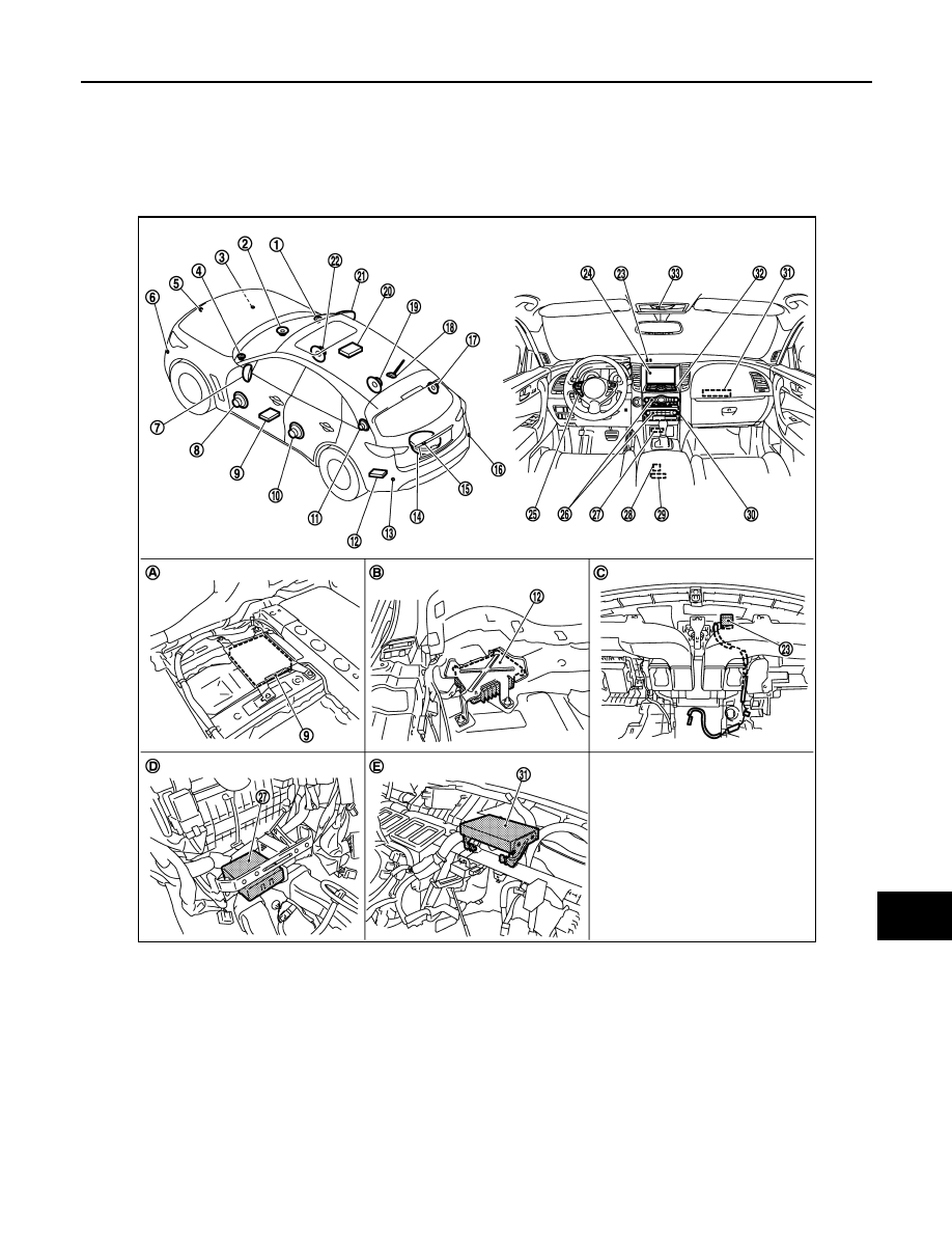
Component Parts Location
INFOID:0000000005503169
1.
Front squawker RH
2.
Center speaker
3.
Corner sensor front RH
4.
Front squawker LH
5.
Front camera
6.
Corner sensor front LH
7.
Side camera LH
8.
Front door speaker LH
9.
Around view monitor control unit
10. Rear door speaker LH
11. Rear squawker LH
12. BOSE amp.
13. Corner sensor rear LH
14. Woofer
15. Rear camera
16. Corner sensor rear RH
17. Rear squawker RH
18. Antenna base (antenna amp. and
satellite antenna)
19. Rear door speaker RH
20. Rear display unit
21. Side camera RH and infrared LED
(auxiliary lighting)
22. Front door speaker RH
23. GPS antenna
24. Front display unit
25. Steering switch
26. Preset switch
27. Sonar control unit
JSNIA2457ZZ

AV-366
< SYSTEM DESCRIPTION >
[NAVIGATION (TWIN MONITOR)]
COMPONENT PARTS
Component Description
INFOID:0000000005503170
28. USB connector
29. Auxiliary input jacks
30. AV control unit
31. Video distributor
32. Multifunction switch
33. Microphone
A.
Under front seat (LH side)
B.
Luggage floor (LH side)
C.
Instrument panel rear side
D.
Console pocket assembly removed
condition
E.
Instrument panel assembly removed
condition
Part name
Description
AV control unit
• Integrates hard disk drive (HDD) allowing map data and music data to be stored.
• It is the master unit of the MULTI AV system, and it is connected to each control
unit by communication. It operates each system according to communication sig-
nals from the AV control unit.
• The AV control unit includes the audio, hands-free phone, voice control, naviga-
tion, USB connection, DVD play, satellite radio and vehicle information functions.
• It is connected to ECM and unified meter and A/C amp. via CAN communication
to obtain necessary information for the vehicle information function.
• It inputs the illumination signals that are required for the front display dimming con-
trol.
• It inputs the signals for driving status recognition (vehicle speed, reverse and park-
ing brake).
• The RGB digital image signal and composite image signal are output to front dis-
play unit.
• Amp. ON signal, sound signal and mode change signal transmitted to BOSE amp.
• Update of map data is performed with the DVD-ROM.
Front display unit
• Front display image is controlled by the serial communication from AV control unit.
• RGB digital image signal is input from AV control unit.
• Composite image signal is input from AV control unit.
• Camera image signal is input from around view monitor control unit.
• Touch panel function can be operated for each system by touching a display di-
rectly.
Rear display unit
• Rear display image is controlled by the serial communication from video distribu-
tor.
• RGB image signal is input from video distributor (RGB image and RGB area).
• Composite image signal [USB (video data), DVD and auxiliary images] is input
from the video distributor.
• Synchronize signal (HP, VP) is output to video distributor.
• It receives the DVD/AUX/USB sound signal from the AV control unit, and then
transmits it to the headphones.
• It operates by receiving the headphone ON signal from the video distributor.
Video distributor
• It receives the image signal from the AV control unit and then transmits it to the
rear display unit.
• It transmits headphone ON signal to rear display unit.
BOSE amp.
• Inputs sound signal from AV control unit, and outputs sound signal to each speak-
er.
• Input mode change signal from AV control unit.
Front door speaker
• Outputs sound signal from BOSE amp.
• Outputs high, mid and low range sounds.
Rear door speaker
• Outputs sound signal from BOSE amp.
• Outputs high, mid and low range sounds.
Front squawker
• Outputs sound signal from BOSE amp.
• Outputs mid range sounds.
Rear squawker
• Outputs sound signal from BOSE amp.
• Outputs mid range sounds.
Center speaker
• Outputs sound signal from BOSE amp.
• Outputs high and mid range sounds.
Woofer
• Inputs power (woofer amp. ON) and sound signal from BOSE amp.
• Outputs low range sounds.

AV
COMPONENT PARTS
AV-367
< SYSTEM DESCRIPTION >
[NAVIGATION (TWIN MONITOR)]
C
D
E
F
G
H
I
J
K
L
M
B
A
O
P
Multifunction switch
• Operation panel is equipped with the centralized switch where audio, auxiliary in-
put and navigation, etc. operations are integrated.
• Connected with preset switch via cable, and operation signal is transmitted to AV
control unit via AV communication.
Preset switch
• Operation panel is equipped with the centralized switch where audio and air con-
ditioner, etc. operations are integrated.
• Connected with multifunction switch via cable, and operation signal is transmitted
to AV control unit via AV communication.
• The disk ejection operating signal is performed by hardwire.
Around view monitor control unit
• It supplies power to front camera, rear camera, and side camera. And then it su-
perimposes the images from each camera and outputs them to front display unit.
• Superimpose the guiding line, predicted course line and sonar indicator to the
camera image that outputs to front display unit.
• It performs the reception/transmission of communication signal with each camera.
• It transmits the sonar operation signal from sonar control unit and receives the so-
nar information from sonar control unit via AV communication.
• It transmits the information received/transmitted with sonar control unit via AV
communication to AV control unit.
Front camera
• It inputs the power supply from around view monitor control unit and outputs the
image of the vehicle front to around view monitor control unit.
• It performs the reception/transmission of the communication signal with around
view monitor control unit.
Rear camera
• It inputs the power supply from around view monitor control unit and outputs the
image of the vehicle rear to around view monitor control unit.
• It performs the reception/transmission of the communication signal with around
view monitor control unit.
Side camera LH
• It inputs the power supply from around view monitor control unit and outputs the
image of the vehicle LH to around view monitor control unit.
• It performs the reception/transmission of the communication signal with around
view monitor control unit.
Side camera RH
• It inputs the power supply from around view monitor control unit and outputs the
image of the vehicle RH to around view monitor control unit.
• It performs the reception/transmission of the communication signal with around
view monitor control unit.
Infrared LED
(Auxiliary lighting)
• It illuminates around the front RH wheel by the power supply from around view
monitor control unit to improve nighttime visibility of front-side view.
• The infrared LED is an invisible light ray.
Sonar control unit
• It is connected with around view monitor control unit via AV communication and
receives the sonar operation signal from around view monitor control unit.
• It transmits the sonar detection status to around view monitor control unit via AV
communication.
• It judges the warning level according to the signal from corner sensor.
Corner sensor
The obstacle distance is detected. The signal is transmitted to sonar control unit.
Steering switch
• Operations for audio, hands-free phone, voice control and navigation, etc. are pos-
sible.
• Steering switch signal (operation signal) is output to AV control unit.
Microphone
• Used for hands-free phone operation and voice recognition.
• Microphone signal is transmitted to AV control unit.
• Power (Microphone VCC) is supplied from AV control unit.
Auxiliary input jacks
Image signal and sound signal of auxiliary input is transmitted to AV control unit.
GPS antenna
GPS signal is received and transmitted to AV control unit.
Part name
Description

AV-368
< SYSTEM DESCRIPTION >
[NAVIGATION (TWIN MONITOR)]
COMPONENT PARTS
*1: Image signals cannot be received from iPod
®
.
Antenna base
A radio antenna base integrated with radio antenna amp. and satellite radio antenna
is adopted.
ANTENNA AMP.
• Radio signal received by rod antenna is amplified and transmitted to AV control
unit.
• Power (antenna amp. ON signal) is supplied from AV control unit.
SATELLITE RADIO ANTENNA
• Receives satellite radio waves and outputs it to AV control unit.
USB connector
Image signal
*1
and sound signal of USB input is transmitted to AV control unit.
Part name
Description
Нет комментариевНе стесняйтесь поделиться с нами вашим ценным мнением.
Текст