Infiniti FX35, FX50 (S51). Manual — part 1858

SHIFT MECHANISM
TM-239
< SYSTEM DESCRIPTION >
[7AT: RE7R01B (VK50VE)]
C
E
F
G
H
I
J
K
L
M
A
B
TM
N
O
P
• Each planetary gear enters the state described below.
Front planetary gear
Under drive planetary gear
Rear planetary gear
Mid planetary gear
Component Parts Location
INFOID:0000000005250214
TM-215, "Cross-Sectional View"
.
Component Description
INFOID:0000000005250215
Name
Front sun gear
Front carrier
Front internal gear
Condition
—
Output
Input
Direction of rotation
Counterclockwise revolution
Clockwise revolution
Clockwise revolution
Number of revolutions
Deceleration from front internal
gear
Deceleration from front internal
gear
Same number of revolution as the
input shaft
Name
Under drive sun gear
Under drive carrier
Under drive internal gear
Condition
—
Fixed
Input/Output
Direction of rotation
Counterclockwise revolution
—
Clockwise revolution
Number of revolutions
Acceleration from under drive inter-
nal gear
—
Same number of revolution as the
front carrier
Name
Rear sun gear
Rear carrier
Rear internal gear
Condition
Output
Fixed
Input
Direction of rotation
Counterclockwise revolution
—
Clockwise revolution
Number of revolutions
Acceleration from rear internal
gear
—
Same number of revolution as the
under drive internal gear
Name
Mid sun gear
Mid carrier
Mid internal gear
Condition
Input
Output
Fixed
Direction of rotation
Counterclockwise revolution
Counterclockwise revolution
—
Number of revolutions
Same number of revolution as the
rear sun gear
Deceleration from mid sun gear
—
Name of the Part (Abbreviation)
Function
Front brake (FR/B)
Fastens the under drive carrier.
Input clutch (I/C)
Connects the mid internal gear and the rear carrier.
Direct clutch (D/C)
Connects the rear carrier and the rear sun gear.
High and low reverse clutch (HLR/C)
Connects the rear sun gear and the mid sun gear.
Reverse brake (R/B)
Fastens the rear carrier.
Low brake (L/B)
Fastens the mid sun gear.
2346 brake (2346/B)
Fastens the under drive sun gear.
1st one-way clutch (1st OWC)
Allows the under drive carrier to turn freely in the forward direction but fastens it for reverse
rotation.
2nd one-way clutch (2nd OWC)
Allows the rear sun gear to turn freely in the forward direction but fastens it for reverse ro-
tation.
Torque converter
Amplifies driving force the engine, and transmits it to transmission input shaft.
Oil pump
Driven by the engine, oil pump supplies oil to torque converter, control valve assembly, and
each lubricating system.
TM-240
< SYSTEM DESCRIPTION >
[7AT: RE7R01B (VK50VE)]
SHIFT LOCK SYSTEM
SHIFT LOCK SYSTEM
System Description
INFOID:0000000005530869
• Shift lock prevents an unintentional start of the vehicle that may be caused by an incorrect operation while
selector lever is in the “P” position.
• Selector lever can be shifted from the “P” position to another position when the following conditions are sat-
isfied.
- Ignition switch ON
- Stop lamp switch is ON (brake pedal is depressed)
- Selector lever knob button is pressed
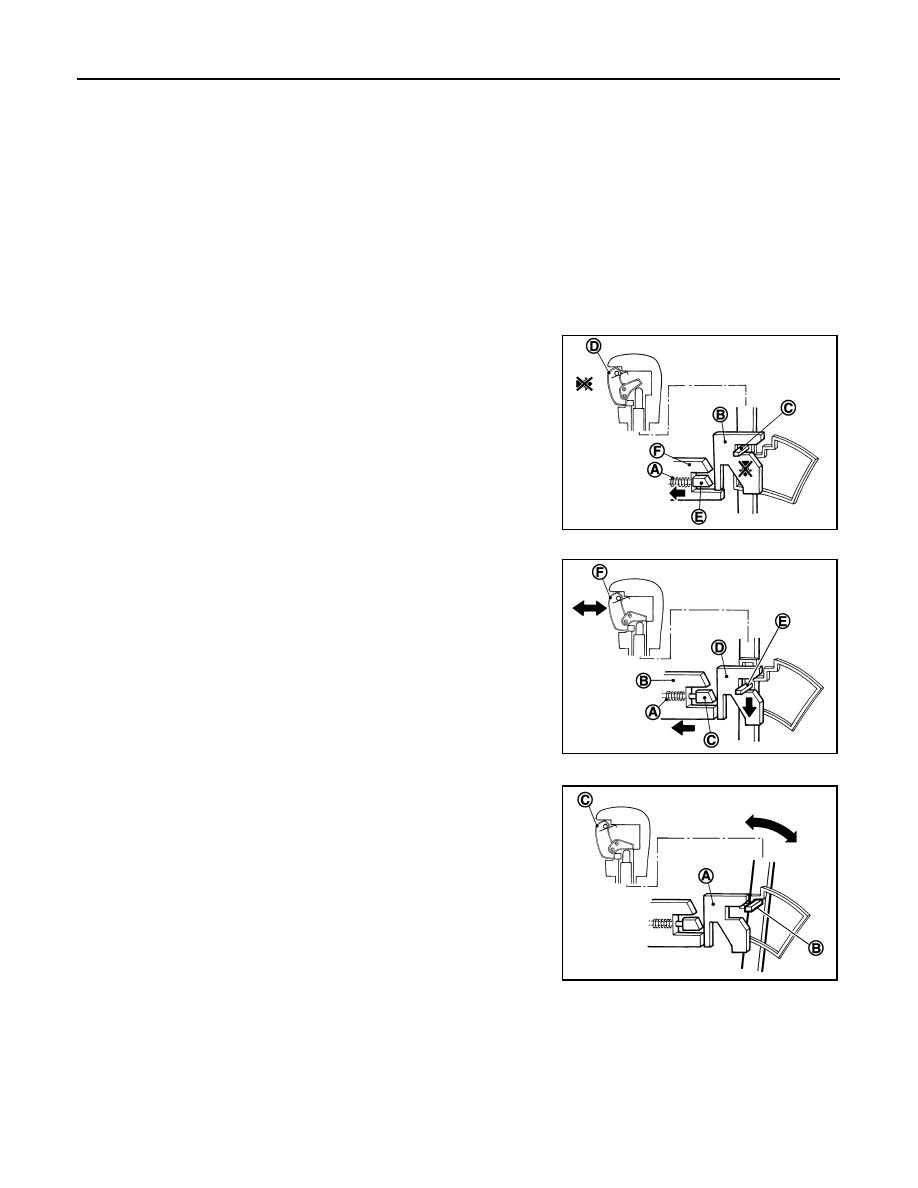
SHIFT LOCK OPERATION AT “P” POSITION
When Brake Pedal Is Not Depressed (No Shift Operation Allowed)
The shift lock solenoid (A) inside the shift lock unit is not energized if
the brake pedal is not depressed while the ignition switch is ON.
The lock plate (B) lowers according to the downward movement of
the position pin (C) when the selector button (D) is pressed, and
presses only slider B (E) into the shift lock unit. Slider A (F) located
below the lock plate prevents the downward movement of the lock
plate with the spring force. The selector lever cannot be shifted from
the “P” position for this reason.
However, slider A is forcibly pressed into the shift lock unit, allowing
the selector lever to shift if the shift lock release button is pressed.
When Brake Pedal Is Depressed (Shift Operation Allowed)
The shift lock solenoid (A) inside the shift lock unit is energized and
the relative positions of sliders A (B) and B (C) are maintained when
the brake pedal is depressed while the ignition switch is ON.
The lock plate (D) lowers according to the downward movement of
the position pin (E), thrusting away sliders A and B, when the selec-
tor button (F) is pressed.
The position pin lowers to the position that allows shift operation for
this reason. As a result, the selector lever can be shifted out of the P
position.
OPERATION AT OTHER THAN “P” POSITION
The shift lock function will not operate at any position other than “P”
because the lock plate (A) is only set for the “P” position. Accord-
ingly, the selector lever can be shifted to any position regardless of
the brake operation.
The position pin (B) enters the “P” position thrusting away the lock
plate when the selector lever is shifted to the “P” position. Then, the
shift mechanism is locked when the selector button (C) is released.
“P” POSITION RETAINING MECHANISM (IGNITION SWITCH LOCK)
When ignition switch is not in the ON position, power is not applied to the shift lock solenoid in the shift lock
unit. This causes shift lock state, and then “P” position is retained.
When an actuating system in the shift lock unit has a malfunction, selector lever is unable to operate from the
“P” position even when pressing the brake pedal with the ignition switch ON. However, when pressing the shift
lock release button, slider A is forcibly pressed into the shift lock unit. This allows shift lock to be released and
selector lever enables the select operation from the “P” position.
CAUTION:
JSDIA0119ZZ
JSDIA0120ZZ
JSDIA0121ZZ
SHIFT LOCK SYSTEM
TM-241
< SYSTEM DESCRIPTION >
[7AT: RE7R01B (VK50VE)]
C
E
F
G
H
I
J
K
L
M
A
B
TM
N
O
P
Never use the shift lock release button except when the select lever is inoperative even when pressing
the brake pedal with the ignition switch ON.
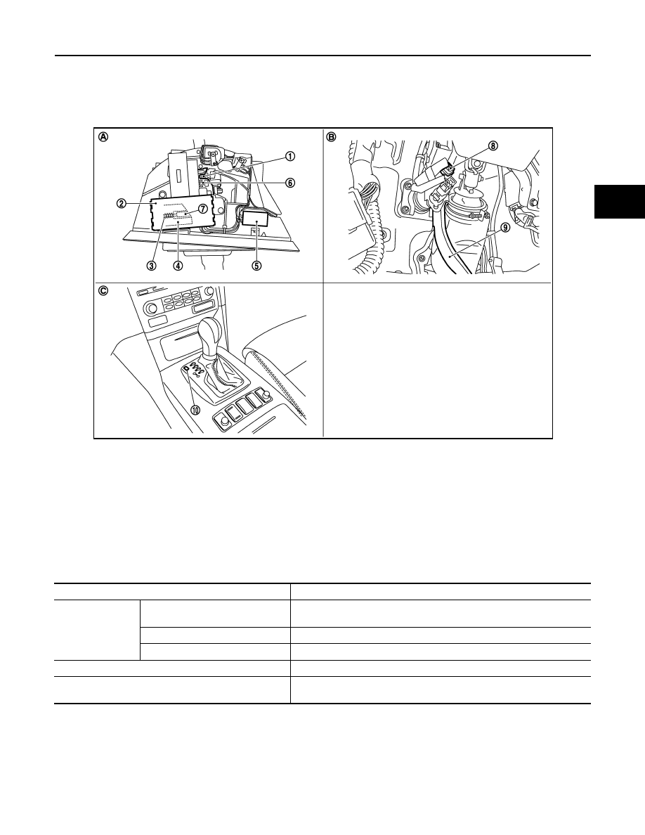
Component Parts Location
INFOID:0000000005530870
*: Shift lock release button becomes operative by removing shift lock cover.
Component Description
INFOID:0000000005530871
1.
Position pin
2.
Shift lock unit
3.
Shift lock solenoid
4.
Slider A
5.
A/T shift selector connector
6.
Lock plate
7.
Slider B
8.
Stop lamp switch
9.
Brake pedal
10. Shift lock cover *
A.
A/T shift selector assembly
B.
Brake pedal, upper
C.
Center console
JSDIA1461ZZ
Component
Function
Shift lock unit
Shift lock solenoid
Activated by the ignition switch and stop lamp signals, it holds the relative
positions of sliders A and B.
Lock plate
Restricts position pin moving.
Shift lock release button
Pressing the shift lock release button cancels the shift lock forcibly.
Position pin
Links with selector knob button and restricts selector lever shift operation.
Stop lamp switch
• When brake pedal is depressed, stop lamp switch turns ON.
• When stop lamp switch turns ON, power is supplied to shift lock unit.
TM-242
< SYSTEM DESCRIPTION >
[7AT: RE7R01B (VK50VE)]
ON BOARD DIAGNOSTIC (OBD) SYSTEM
ON BOARD DIAGNOSTIC (OBD) SYSTEM
Diagnosis Description
INFOID:0000000005250219
The A/T system has two self-diagnostic systems.
The first is the emission-related on board diagnostic system (OBD-II) performed by the TCM in combination
with the ECM. A malfunction is indicated by the MIL (malfunction indicator lamp) and is stored as a DTC in the
ECM memory and in the TCM memory.
The second is the TCM original self-diagnosis indicated by the TCM. A malfunction history is stored in the
TCM memory. The detected items are overlapped with OBD-II self-diagnostic items. For details, refer to
.
OBD FUNCTION
The ECM provides emission-related on board diagnostic (OBD-II) functions for the A/T system.
One function is to receive a signal from the TCM used with OBD-related parts of the A/T system. The signal is
sent to the ECM when a malfunction occurs in the corresponding OBD-related part.
The other function is to indicate a diagnostic result by means of the MIL (malfunction indicator lamp) on the
instrument panel. Sensors, switches and solenoid valves are used as sensing elements.
The MIL automatically illuminates in “One or Two Trip Detection Logic” when a malfunction is sensed in rela-
tion to A/T system parts. For details, refer to
EC-705, "Diagnosis Description"
.
Нет комментариевНе стесняйтесь поделиться с нами вашим ценным мнением.
Текст