Infiniti FX35, FX50 (S51). Manual — part 353

CCS-232
< DTC/CIRCUIT DIAGNOSIS >
[DCA]
C1A10 RELEASE SWITCH
C1A10 RELEASE SWITCH
Description
INFOID:0000000005501816
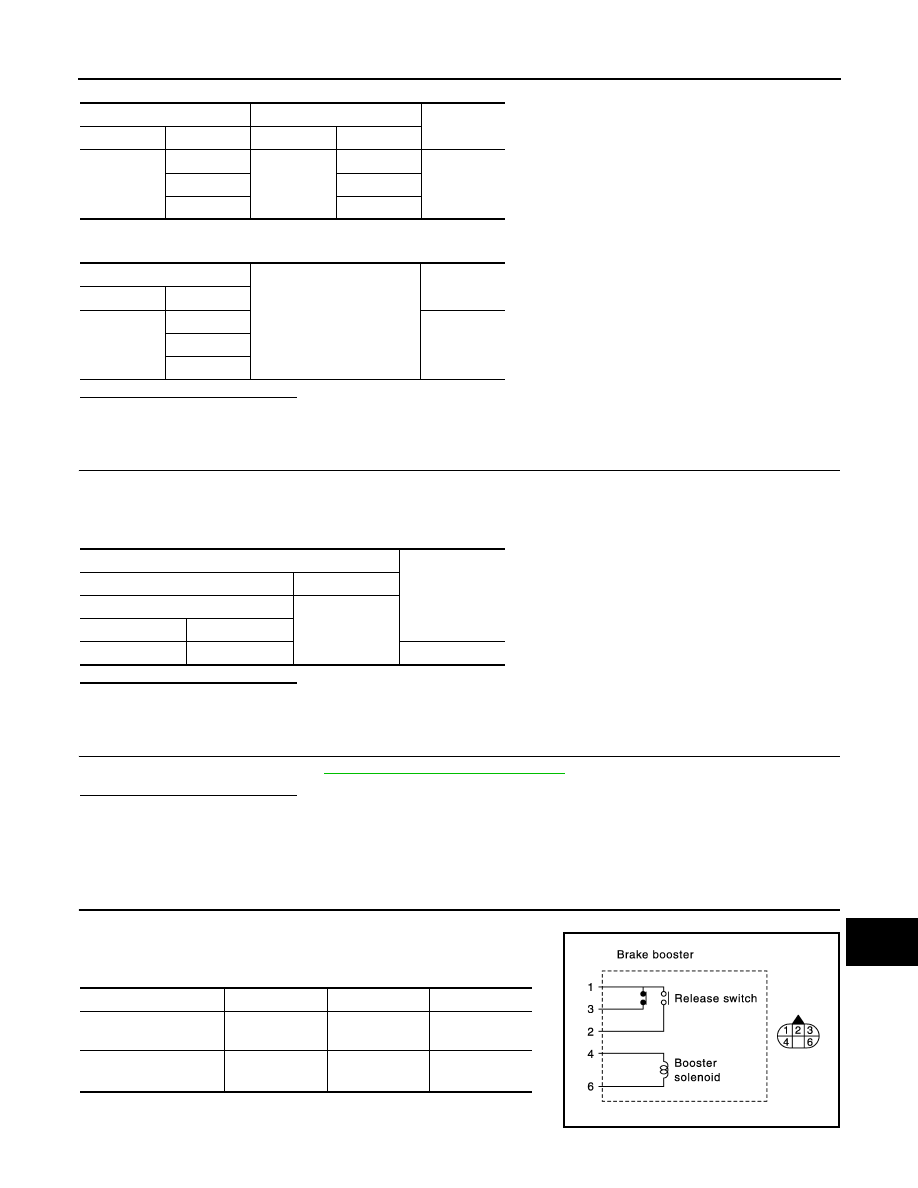
• The release switch is integrated with the brake booster.
• The release switch detects that the driver depresses the brake pedal, and it outputs the signal to the brake
booster control unit.
• The brake booster control unit transmits the release switch signal [release switch NO signal (normal open),
release switch NC signal (normal close)] to the ICC sensor integrated unit via ITS communication.
DTC logic
INFOID:0000000005501817
DTC DETECTION LOGIC
NOTE:
If DTC “C1A10” is detected along with DTC “U1000”, first diagnose the DTC “U1000”. Refer to
SENSOR INTEGRATED UNIT : DTC Logic"
DTC CONFIRMATION PROCEDURE
1.
PERFORM DTC CONFIRMATION PROCEDURE (1)
1.
Start the engine.
2.
Turn the DCA system ON, and wait for 5 minutes or more.
3.
Perform “All DTC Reading” with CONSULT-III.
4.
Check if the “C1A10” is detected as the current malfunction in self-diagnosis results of “ICC”.
Is “C1A10” detected as the current malfunction?
YES
>> Refer to
CCS-232, "Diagnosis Procedure"
NO
>> GO TO 2.
2.
PERFORM DTC CONFIRMATION PROCEDURE (2)
1.
Depress the brake pedal strongly 10 times or more.
2.
Perform “All DTC Reading”.
3.
Check if the “C1A10” is detected as the current malfunction in self-diagnosis results of “ICC”.
Is “C1A10” detected as the current malfunction?
YES
>> Refer to
CCS-232, "Diagnosis Procedure"
NO
>> Refer to
GI-36, "Intermittent Incident"
.
Diagnosis Procedure
INFOID:0000000005501818
1.
CHECK SELF-DIAGNOSIS RESULTS
Check if “U1000” is detected other than “C1A10” in “Self Diagnostic Result” of “ICC”.
Is “U1000” detected?
YES
>> Perform the CAN communication system inspection. Repair or replace the malfunctioning parts.
CCS-313, "ICC SENSOR INTEGRATED UNIT : DTC Logic"
.
NO
>> GO TO 2.
2.
CHECK HARNESS BETWEEN BRAKE BOOSTER (RELEASE SWITCH) AND BRAKE BOOSTER CON-
TROL UNIT
1.
Turn the ignition switch OFF.
2.
Disconnect connectors of brake booster and brake booster control unit.
3.
Check for continuity between the brake booster control unit harness connector and brake booster harness
connector.
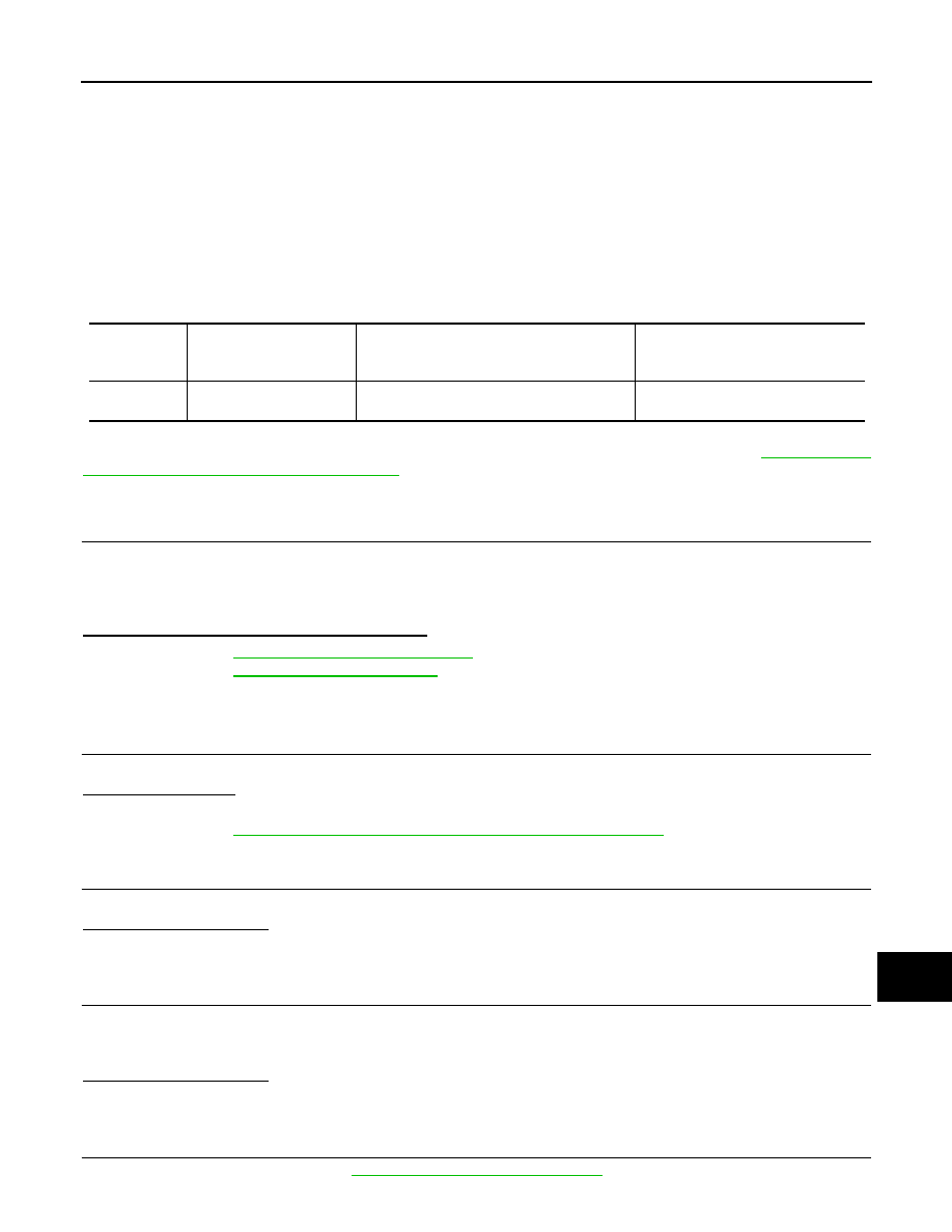
DTC
(On board dis-
play)
Trouble diagnosis name
DTC detecting condition
Possible causes
C1A10
(10)
RELEASE SW CIRC
If the release switch NO signal and the release
switch NC signal, received from the brake
booster control unit via ITS communication,
are inconsistent
• Release switch
• Release switch circuit
• Brake booster control unit
CCS
C1A10 RELEASE SWITCH
CCS-233
< DTC/CIRCUIT DIAGNOSIS >
[DCA]
C
D
E
F
G
H
I
J
K
L
M
B
N
P
A
4.
Check for continuity between brake booster control unit harness connector and ground.
Is the inspection result normal?
YES
>> GO TO 3.
NO
>> Repair the harnesses or connectors.
3.
CHECK RELEASE SWITCH POWER SUPPLY CIRCUIT
1.
Connect the brake booster control unit connector.
2.
Turn the ignition switch ON.
3.
Check voltage between brake booster control unit harness connector and ground.
Is the inspection result normal?
YES
>> GO TO 4.
NO
>> Replace the brake booster control unit.
4.
CHECK RELEASE SWITCH
Check the release switch. Refer to
CCS-233, "Component Inspection"
.
Is the inspection result normal?
YES
>> Replace the brake booster control unit.
NO
>> Replace the brake booster.
Component Inspection
INFOID:0000000005501819
1.
CHECK BRAKE BOOSTER (RELEASE SWITCH)
Check for continuity between brake booster (release switch) termi-
nals.
NOTE:
If the depressing force is weak, it may not be changed.
Brake booster control unit
Brake booster
Continuity
Connector
Terminal
Connector
Terminal
B250
6
E44
1
Existed
15
3
22
2
Brake booster control unit
Ground
Continuity
Connector
Terminal
B250
6
Not existed
15
22
Terminal
Voltage
(Approx.)
(+)
(–)
Brake booster control unit
Ground
Connector
Terminal
B250
6
10 V
Condition
1 – 3
1 – 2
2 – 3
Brake pedal not de-
pressed
Continuity
No continuity
No continuity
Brake pedal depressed
No continu-
ity
NOTE
Continuity
NOTE
No continuity
JPOIA0160GB

CCS-234
< DTC/CIRCUIT DIAGNOSIS >
[DCA]
C1A10 RELEASE SWITCH
Is the inspection result normal?
YES
>> INSPECTION END
NO
>> Replace the brake booster.
Special Repair Requirement
INFOID:0000000005501820
DESCRIPTION
Perform the action test after adjusting the laser beam aiming of ICC sensor integrated unit when the following
operation is performed.
• Removal and installation of ICC sensor integrated unit
• Replacement of ICC sensor integrated unit
SPECIAL REPAIR REQUIREMENT
1.
LASER BEAM AIMING ADJUSTMENT OF ICC SENSOR INTEGRATED UNIT
Adjust the laser beam aiming of the ICC sensor integrated unit. Refer to
>> GO TO 2.
2.
CHECK DCA SYSTEM
1.
Erase the “self-diagnosis results”, and then perform “All DTC Reading” again after performing the action
test. (Refer to
CCS-191, "ACTION TEST : Description"
for action test.)
2.
Check that the DCA system is normal.
>> WORK END
CCS
C1A11 PRESSURE CONTROL
CCS-235
< DTC/CIRCUIT DIAGNOSIS >
[DCA]
C
D
E
F
G
H
I
J
K
L
M
B
N
P
A
C1A11 PRESSURE CONTROL
Description
INFOID:0000000005501821
• The brake booster control unit receives the brake fluid pressure command signal from ICC sensor integrated
unit via ITS communication and activates the booster solenoid to operate the brake booster.
• The brake booster adjusts the brake fluid pressure by driving the booster solenoid.
• The brake pedal is controlled when the brake booster adjusts the brake fluid pressure.
DTC Logic
INFOID:0000000005501822
DTC DETECTION LOGIC
NOTE:
If DTC “C1A11” is detected along with DTC “U1000”, first diagnose the DTC “U1000”. Refer to
SENSOR INTEGRATED UNIT : DTC Logic"
DTC CONFIRMATION PROCEDURE
1.
PERFORM DTC CONFIRMATION PROCEDURE
1.
Start the engine.
2.
Perform the active test item “BOOSTER SOL/V” with CONSULT-III.
3.
Perform “All DTC Reading”.
4.
Check if the “C1A11” is detected as the current malfunction in self-diagnosis results of “ICC”.
Is “C1A11” detected as the current malfunction?
YES
>> Refer to
CCS-235, "Diagnosis Procedure"
NO
>> Refer to
GI-36, "Intermittent Incident"
.
Diagnosis Procedure
INFOID:0000000005501823
1.
CHECK SELF-DIAGNOSIS RESULTS
Check if “U1000” is detected other than “C1A11” in “Self Diagnostic Result” of “ICC”.
Is “U1000” detected?
YES
>> Perform the CAN communication system inspection. Repair or replace the malfunctioning parts.
CCS-313, "ICC SENSOR INTEGRATED UNIT : DTC Logic"
.
NO
>> GO TO 2.
2.
CHECK BRAKE OPERATION
Check if the brake operates normally.
Does it operate normally?
YES
>> GO TO 4.
NO
>> GO TO 3.
3.
BRAKE LINE INSPECTION
1.
Check the brake system, and then repair malfunctioning parts.
2.
Erases All self-diagnosis results.
3.
Perform “BOOSTER SOL/V” on “Active Test” of “ICC”.
Does it operate normally?
YES
>> INSPECTION END
NO
>> GO TO 4.
4.
CHECK BOOSTER SOLENOID
Check the booster solenoid. Refer to
CCS-236, "Component Inspection"
DTC
(On board dis-
play)
Trouble diagnosis name
DTC detecting condition
Possible causes
C1A11
(11)
PRESSURE CONTROL
If the brake booster is malfunctioning
Brake booster
Нет комментариевНе стесняйтесь поделиться с нами вашим ценным мнением.
Текст