Infiniti FX35, FX50 (S51). Manual — part 412
CCS-468
< SYSTEM DESCRIPTION >
[LDW & LDP]
DIAGNOSIS SYSTEM [ABS ACTUATOR AND ELECTRIC UNIT (CONTROL
UNIT)]
OFF LAMP
(On/Off)
×
VDC OFF indicator lamp
SLIP LAMP
(On/Off)
×
SLIP indicator lamp
FLUID LEV SW
(On/Off)
Brake fluid level switch signal status
PARK BRAKE SW
(On/Off)
Parking brake switch signal status
EBD SIGNAL
(On/Off)
EBD operation
ABS SIGNAL
(On/Off)
ABS operation
TCS SIGNAL
(On/Off)
TCS operation
VDC SIGNAL
(On/Off)
VDC operation
ABS FAIL SIG
(On/Off)
ABS fail-safe signal
TCS FAIL SIG
(On/Off)
TCS fail-safe signal
VDC FAIL SIG
(On/Off)
VDC fail-safe signal
CRANKING SIG
(On/Off)
Crank operation
USV[FR-RL]
(On/Off) (Note 1)
VDC switch-over valve
USV[FL-RR]
(On/Off) (Note 1)
HSV[FR-RL]
(On/Off) (Note 1)
HSV[FL-RR]
(On/Off) (Note 1)
BST OPER SIG
(On/Off)
Booster operation signal
V/R OUTPUT
(On/Off)
Solenoid valve relay activated
M/R OUTPUT
(On/Off)
Actuator motor and motor relay activated
LDP) APP SEN
(%) (Note 2)
×
×
Accelerator pedal position sensor status received from
ECM via CAN communication
LDP) ICC MAIN SW
(On/Off) (Note 2)
×
×
ICC main switch status received from ECM via CAN com-
munication
LDP) LDP ON SW
(On/Off) (Note 2)
×
×
LDP switch status received from ECM via CAN communi-
cation
LDP) WIPER SIGNAL
(Stop/PRTCT/1low/1high/Low/High)
(Note 2)
×
×
Front wiper operating condition received from BCM via
CAN communication
LDP) BRAKE SW
(On/Off) (Note 2)
×
×
Brake switch signal status
LDP) STOP LMP SW
(On/Off) (Note 2)
×
×
Stop lamp switch signal status
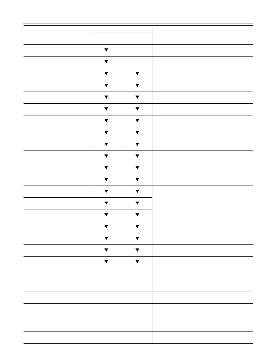
Monitor item (Unit)
SELECT MONITOR ITEM
Remarks
ECU INPUT
SIGNALS
MAIN SIGNALS

CCS
DIAGNOSIS SYSTEM [ABS ACTUATOR AND ELECTRIC UNIT (CONTROL
UNIT)]
CCS-469
< SYSTEM DESCRIPTION >
[LDW & LDP]
C
D
E
F
G
H
I
J
K
L
M
B
N
P
A
NOTE:
1: A brief moment of On/Off condition occurs every 20 seconds after ignition switch turned ON. This is not malfunction because it is an
operation for checking.
2: With LDP models.
ACTIVE TEST
CAUTION:
• Never perform active test while driving vehicle.
• Make sure to completely bleed air from brake system.
• The active test cannot be started when ABS warning lamp, VDC OFF indicator lamp, SLIP indicator
lamp and brake warning lamp are ON.
• ABS warning lamp, VDC OFF indicator lamp, SLIP indicator lamp and brake warning lamp are ON
during active test.
• Erase memory of the lane camera unit after implementing active test. Refer to
NOTE:
• When active test is performed while depressing the pedal, the pedal depression amount will change. This is
normal. (Only solenoid valve and ABS motor.)
• “TEST IS STOPPED” in “ABS” with CONSULT-III is displayed 10 seconds after operation start.
• After “TEST IS STOPPED” in “ABS” with CONSULT-III is displayed, to perform test again.
Test Item
ABS SOLENOID VALVE
• Select “Up”, “Keep” and “Down” of “ACTIVE TEST” in “ABS” with CONSULT-III. Then use screen monitor to
check that solenoid valve operates as shown in the table below.
LDP) LDW SW
(On/Off) (Note 2)
×
×
LDW switch status received from lane camera unit via
CAN communication
LDP) SHIFT POSITION
(OFF/P/R/N/D/MM 1st – MM 7th)
(Note 2)
×
×
Shift position received from TCM via CAN communication
LDP) TURN SIGNAL
(Off/LH/RH/LH&RH) (Note 2)
×
×
Turn signal operating condition received from BCM via
CAN communication
Monitor item (Unit)
SELECT MONITOR ITEM
Remarks
ECU INPUT
SIGNALS
MAIN SIGNALS
Test item
Display item
Display (Note)
Up
Keep
Down
FR RH SOL
FR RH IN SOL
Off
On
On
FR RH OUT SOL
Off
Off
On*
USV[FR-RL]
Off
Off
Off
HSV[FR-RL]
Off
Off
Off
FR LH SOL
FR LH IN SOL
Off
On
On
FR LH OUT SOL
Off
Off
On*
USV[FL-RR]
Off
Off
Off
HSV[FL-RR]
Off
Off
Off
RR RH SOL
RR RH IN SOL
Off
On
On
RR RH OUT SOL
Off
Off
On*
USV[FL-RR]
Off
Off
Off
HSV[FL-RR]
Off
Off
Off

CCS-470
< SYSTEM DESCRIPTION >
[LDW & LDP]
DIAGNOSIS SYSTEM [ABS ACTUATOR AND ELECTRIC UNIT (CONTROL
UNIT)]
*: On for 1 to 2 seconds after the select, and then Off.
NOTE:
A brief moment of On/Off condition occurs every 20 seconds after ignition switch turned ON. This is not malfunction because it is an
operation for checking.
ABS SOLENOID VALVE (ACT)
• Select “Up”, “ACT UP” and “ACT KEEP” of “ACTIVE TEST” in “ABS” with CONSULT-III. Then use screen
monitor to check that solenoid valve operates as shown in the table below.
*: On for 1 to 2 seconds after the select, and then Off.
NOTE:
A brief moment of On/Off condition occurs every 20 seconds after ignition switch turned ON. This is not malfunction because it is an
operation for checking.
ABS MOTOR
• Select “On” and “Off” of “ACTIVE TEST” in “ABS” with CONSULT-III. Make sure motor relay and actuator
relay operates as shown in table below.
NOTE:
A brief moment of On/Off condition occurs every 20 seconds after ignition switch turned ON. This is not malfunction because it is an
operation for checking.
ECU IDENTIFICATION
RR LH SOL
RR LH IN SOL
Off
On
On
RR LH OUT SOL
Off
Off
On*
USV[FR-RL]
Off
Off
Off
HSV[FR-RL]
Off
Off
Off
Test item
Display item
Display (Note)
Up
Keep
Down
Test item
Display item
Display (Note)
Up
ACT UP
ACT KEEP
FR RH ABS SOLENOID
(ACT)
FR RH IN SOL
Off
Off
Off
FR RH OUT SOL
Off
Off
Off
USV[FR-RL]
Off
On
On
HSV[FR-RL]
Off
On*
Off
FR LH ABS SOLENOID
(ACT)
FR LH IN SOL
Off
Off
Off
FR LH OUT SOL
Off
Off
Off
USV[FL-RR]
Off
On
On
HSV[FL-RR]
Off
On*
Off
RR RH ABS SOLENOID
(ACT)
RR RH IN SOL
Off
Off
Off
RR RH OUT SOL
Off
Off
Off
USV[FL-RR]
Off
On
On
HSV[FL-RR]
Off
On*
Off
RR LH ABS SOLENOID
(ACT)
RR LH IN SOL
Off
Off
Off
RR LH OUT SOL
Off
Off
Off
USV[FR-RL]
Off
On
On
HSV[FR-RL]
Off
On*
Off
Test item
Display item
Display
On
Off
ABS MOTOR
MOTOR RELAY
On
Off
ACTUATOR RLY (Note)
On
On

CCS
DIAGNOSIS SYSTEM [ABS ACTUATOR AND ELECTRIC UNIT (CONTROL
UNIT)]
CCS-471
< SYSTEM DESCRIPTION >
[LDW & LDP]
C
D
E
F
G
H
I
J
K
L
M
B
N
P
A
ABS actuator and electric unit (control unit) part number can be read.
SPECIFIC FUNCTION
Specific Data Monitor
Specific data monitor displays specific LDP operating conditions.
Monitor item (Unit)
Remarks
YAW RATE SEN
(d/s)
Yaw rate detected by yaw rate/side G sensor
LDP) YAW ORDER
(
×
100Nm)
Calculated target yaw moment
LDP) WARN REQ
(On/Off)
Status of warning request that transmits to lane camera unit via CAN communi-
cation
LDP) WARN control
(On/Off)
Status of warning main controller for LDP
LDP) REDY signal
(On/Off)
Status of internal judgment by LDP controller [ABS actuator and electric unit
(control unit)]
LDP) STATUS signal
(STANDBY/WARN/MASK/Off)
Status of internal judgment by LDP controller [ABS actuator and electric unit
(control unit)]
LDP) Camera lost
(Detect/Deviate/Both)
Lane marker detected condition received from lane camera unit via CAN com-
munication
LDP) Lane unclear
(On/Off)
Lane marker condition received from lane camera unit via CAN communication
Нет комментариевНе стесняйтесь поделиться с нами вашим ценным мнением.
Текст