Infiniti FX35, FX50 (S51). Manual — part 985
EM-240
< UNIT DISASSEMBLY AND ASSEMBLY >
[VK50VE]
CAMSHAFT
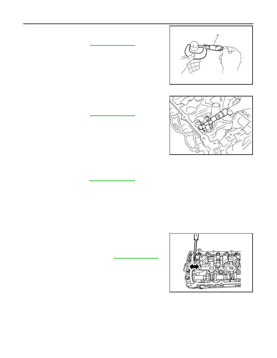
• Measure the outer diameter at 1/2 height of valve lifter with a
micrometer (A) since valve lifter is in barrel shape.
VALVE LIFTER HOLE DIAMETER
• Measure the inner diameter of valve lifter hole of cylinder head with
an inside micrometer.
VALVE LIFTER CLEARANCE
• (Valve lifter clearance) = (Valve lifter hole diameter) – (Valve lifter outer diameter)
• If the calculated value is out of the standard, referring to each standard of valve lifter outer diameter and
valve lifter hole diameter, replace either or both valve lifter and VVEL ladder assembly & cylinder head
assembly.
NOTE:
Cylinder head assembly cannot be replaced as a single part, because it is machined together with VVEL lad-
der assembly.
INSPECTION AFTER DISASSEMBLY (INTAKE SIDE)
Drive Shaft End Play
• Install a dial indicator in thrust direction on front end of drive shaft.
Measure the end play of a dial indicator when drive shaft is moved
forward/backward (in direction of axis).
Standard
: Refer to
.
JPBIA0125ZZ
Standard
: Refer to
.
SEM867E
Standard
: Refer to
.
Standard and limit
: Refer to
.
JPBIA1337ZZ
CAMSHAFT
EM-241
< UNIT DISASSEMBLY AND ASSEMBLY >
[VK50VE]
C
D
E
F
G
H
I
J
K
L
M
A
EM
N
P
O
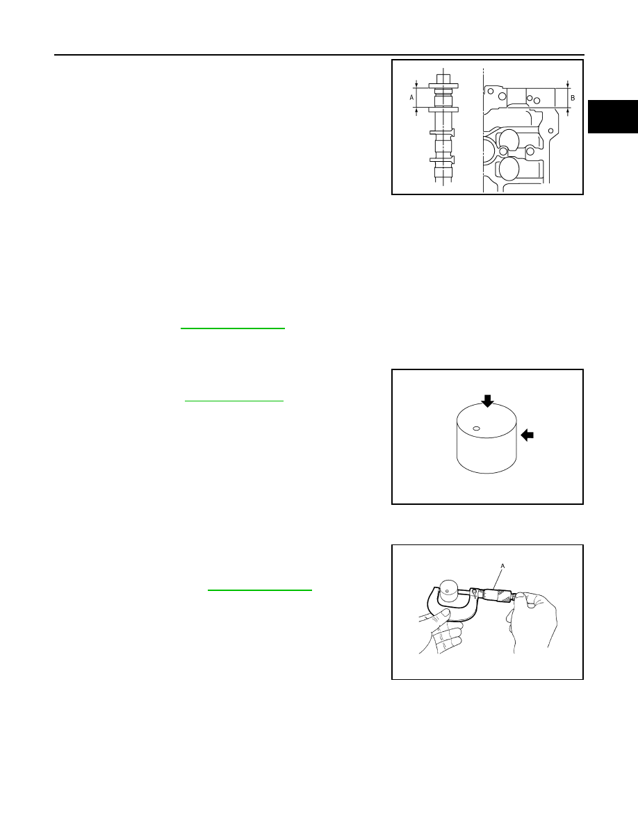
• Measure the following parts if out of the limit.
- Dimension “A” for drive shaft No. 1 journal
- Dimension “B” for cylinder head No. 1 journal bearing
• If it exceeds the limit, replace VVEL ladder assembly & cylinder
head assembly.
NOTE:
Cylinder head assembly cannot be replaced as a single part,
because it is machined together with VVEL ladder assembly.
Camshaft Sprocket (INT) Runout
1.
Put V-block on precise flat table, and support No. 2 and 5 journals of drive shaft.
CAUTION:
Never support No. 1 journal (on the side of camshaft sprocket) because it has a different diameter
from the other four locations.
2.
Measure the camshaft sprocket (INT) runout with a dial indicator. (Total indicator reading)
3.
If it exceeds the limit, replace camshaft sprocket (INT).
Valve Lifter (INT)
• Check if surface of valve lifter has any wear or crack.
• If wear or crack is found, replace VVEL ladder assembly & cylinder
head assembly. Refer to
.
NOTE:
Since the valve lifter (INT) cannot be replaced by the piece, VVEL
ladder assembly & cylinder head assembly replacement are
required.
Valve Lifter Clearance (INT)
VALVE LIFTER OUTER DIAMETER
• Measure the outer diameter at 1/2 height of valve lifter (INT) with a
micrometer (A) since valve lifter is in barrel shape.
VALVE LIFTER HOLE DIAMETER
Standard
: 30.500 - 30.548 mm (1.2008 - 1.2027 in)
Standard
: 30.360 - 30.385 mm (1.1953 - 1.1963 in)
KBIA2404J
Limit
: Refer to
KBIA0182E
Standard
: Refer to
.
JPBIA0125ZZ
EM-242
< UNIT DISASSEMBLY AND ASSEMBLY >
[VK50VE]
CAMSHAFT
• Measure the inner diameter of valve lifter hole of cylinder head with
an inside micrometer.
VALVE LIFTER CLEARANCE
• (Valve lifter clearance) = (Valve lifter hole diameter) – (Valve lifter outer diameter)
• If the calculated value is out of the standard, replace VVEL ladder assembly & cylinder head assembly.
NOTE:
Since the valve lifter (INT) cannot be replaced by the piece, VVEL ladder assembly & cylinder head assem-
bly replacement are required.
VVEL Ladder Assembly
DRIVE SHAFT OPERATIONAL CHECK
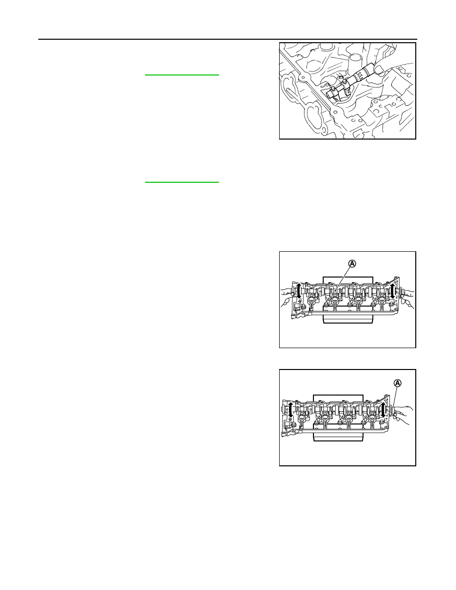
• Hold the both ends of the drive shaft (A) and rotate it to check that
it rotates smoothly.
CAUTION:
Turn VVEL ladder assembly upside down to prevent the drive
shaft from dropping off.
CONTROL SHAFT OPERATIONAL CHECK
• Move control shaft (A) to the small stopper and large stopper to
check that the control shaft functions smoothly.
CAUTION:
Turn VVEL ladder assembly upside down to prevent the drive
shaft from dropping off.
RINK CHECK FOR BACK-LASH (BONDING)
Standard
: Refer to
.
SEM867E
Standard
: Refer to
.
JPBIA2135ZZ
JPBIA2136ZZ
CAMSHAFT
EM-243
< UNIT DISASSEMBLY AND ASSEMBLY >
[VK50VE]
C
D
E
F
G
H
I
J
K
L
M
A
EM
N
P
O
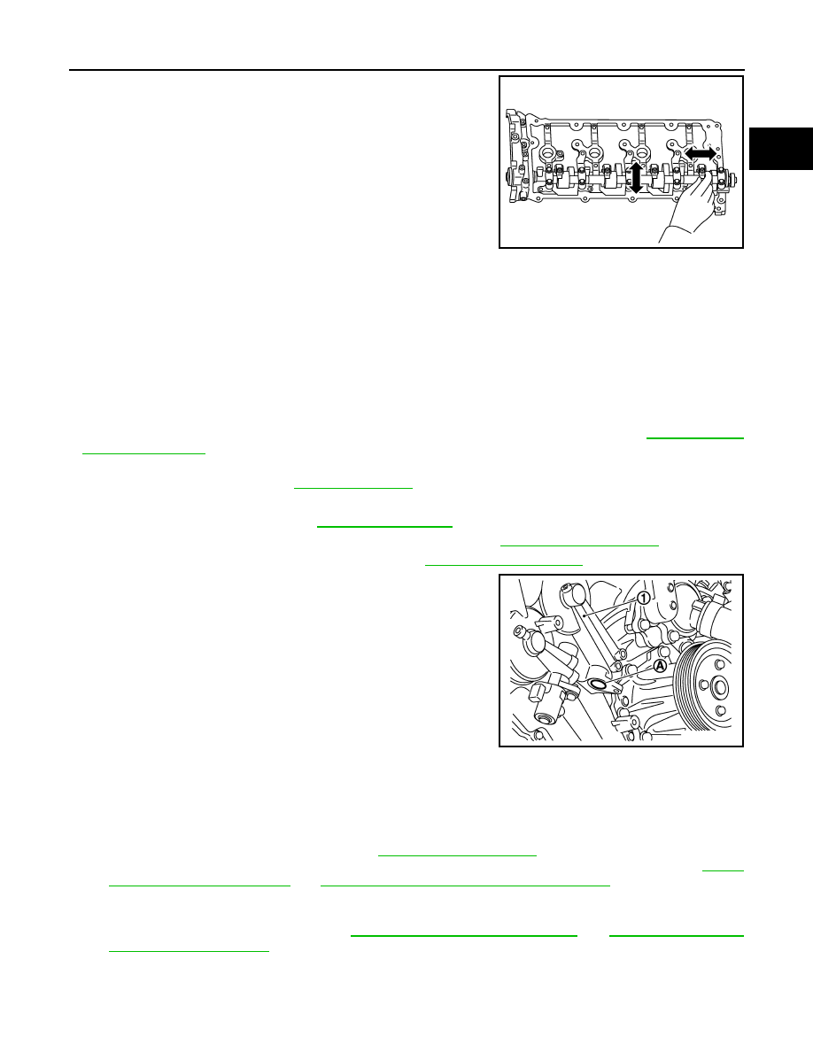
• Check that the link and the shaft of drive shaft and control shaft are
not fixed.
• Check this by moving drive shaft and control shaft in the axial and
rotation directions.
• If there is an unusualness related to the above three items, replace VVEL ladder assembly & cylinder head
assembly.
NOTE:
VVEL ladder assembly cannot be replaced as a single part, because it is machined together with cylinder
head assembly.
INSPECTION AFTER ASSEMBLY
Inspection of Camshaft Sprocket (INT) Oil Groove
CAUTION:
• Perform this inspection only when DTC P0011, P0012 is detected in self-diagnostic results of CON-
SULT-III and it is directed according to inspection procedure of EC section. Refer to
.
• Check when engine is cold to prevent burns from the splashing engine oil.
1.
Check engine oil level. Refer to
2.
Perform the following procedure to prevent the engine from being unintentionally started while checking.
a.
Release the fuel pressure. Refer to
.
b.
Disconnect ignition coil and injector harness connectors. Refer to
3.
Remove valve timing control solenoid valve. Refer to
.
4.
Crank engine, and then check that engine oil comes out from
valve timing control solenoid valve hole (A). End crank after
checking.
WARNING:
Be careful not to touch rotating parts (drive belt, idler pul-
ley, and crankshaft pulley, etc.).
CAUTION:
• Prevent splashing by using a shop cloth to prevent the
worker from injury from engine oil and to prevent engine
oil contamination.
• Prevent splashing by using a shop cloth to prevent engine oil from being splashed to engine and
vehicle. Especially, be careful not to apply engine oil to rubber parts of drive belt, engine mount-
ing insulator, etc. Wipe engine oil out immediately if it is splashed.
5.
Perform the following inspection if engine oil does not come out from valve timing control solenoid valve
oil hole of the valve timing control cover.
• Remove oil filter, and then clean it. Refer to
• Clean oil groove between oil strainer and valve timing control solenoid valve. Refer to
LU-22, "Engine Lubrication System Schematic"
.
6.
Remove components between valve timing control solenoid valve and camshaft sprocket, and then check
each oil groove for clogging.
• Clean oil groove if necessary. Refer to
LU-21, "Engine Lubrication System"
.
7.
After inspection, install removed parts in the reverse order.
Inspection for Leakage
JPBIA2137ZZ
1
: Valve timing control cover (bank 2)
JPBIA2138ZZ
Нет комментариевНе стесняйтесь поделиться с нами вашим ценным мнением.
Текст