Infiniti FX35, FX50 (S51). Manual — part 444
WATER PUMP
CO-21
< REMOVAL AND INSTALLATION >
[VQ35HR]
C
D
E
F
G
H
I
J
K
L
M
A
CO
N
P
O
b.
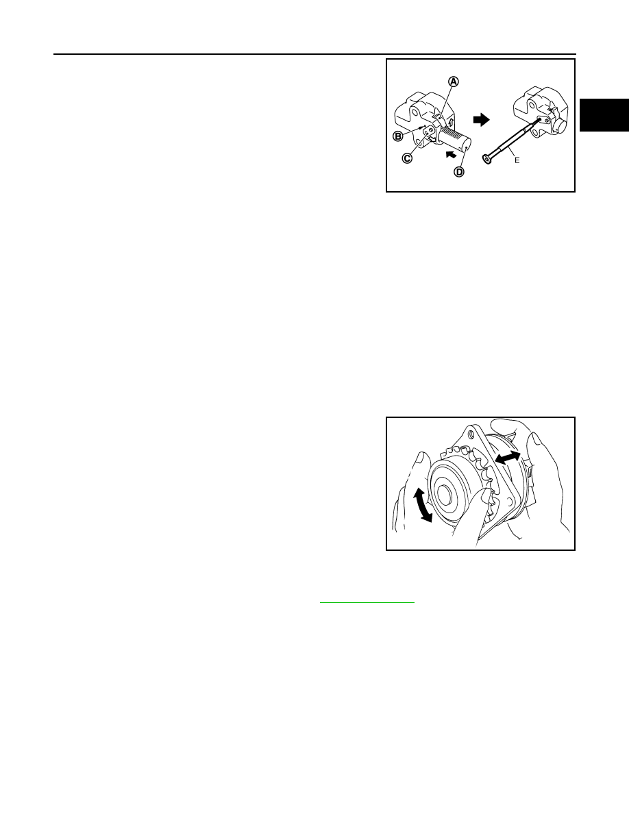
Pull plunger stopper tab (A) up (or turn lever downward) so as to
remove plunger stopper tab from the ratchet of plunger (D).
NOTE:
Plunger stopper tab and lever (C) are synchronized.
c.
Push plunger into the inside of tensioner body.
d.
Hold plunger in the fully compressed position by engaging
plunger stopper tab with the tip of ratchet.
e.
To secure lever, insert stopper pin (E) through hole of lever into
tensioner body hole (B).
• The lever parts and the tab are synchronized. Therefore, the
plunger will be secured under this condition.
NOTE:
Figure shows the example of 1.2 mm (0.047 in) diameter thin screwdriver being used as the stopper pin.
f.
Install timing chain tensioner (primary).
• Remove dust and foreign material completely from backside of timing chain tensioner (primary) and
from installation area of rear timing chain case.
g.
Remove stopper pin.
h.
Check again that timing chain and water pump sprocket are engaged.
4.
Install in the reverse order of removal for remaining parts.
• After starting engine, let idle for three minutes, then rev engine up to 3,000 rpm under no load to
purge air from the high-pressure chamber of chain tensioner. Engine may produce a rattling
noise. This indicates that air still remains in the chamber and is not a matter of concern.
Inspection
INFOID:0000000005246369
INSPECTION AFTER REMOVAL
• Check for badly rusted or corroded water pump body assembly.
• Check for rough operation due to excessive end play.
• If anything is found, replace water pump.
INSPECTION AFTER INSTALLATION
• Check that the reservoir tank cap is tightened.
• Check for leakage of engine coolant using the radiator cap tester adapter (commercial service tool) and the
radiator cap tester (commercial service tool). Refer to
• Start and warm up the engine. Visually check that there is no leakage of engine coolant.
JPBIA0118ZZ
SLC943A
CO-22
< REMOVAL AND INSTALLATION >
[VQ35HR]
WATER INLET AND THERMOSTAT ASSEMBLY
WATER INLET AND THERMOSTAT ASSEMBLY
Exploded View
INFOID:0000000005246370
Removal and Installation
INFOID:0000000005246371
REMOVAL
1.
Remove engine cover. Refer to
2.
Remove air duct and air cleaner case assembly (bank 2). Refer to
.
3.
Remove reservoir tank. Refer to
.
4.
Remove engine undercover with a power tool.
5.
Drain engine coolant from radiator drain plug at the bottom of radiator. Refer to
CAUTION:
• Perform this step when the engine is cold.
• Never spill engine coolant on drive belt.
6.
Disconnect radiator hose (lower).
7.
Disconnect intake valve timing control solenoid valve harness connector (bank 2), and remove intake
valve timing control solenoid valve.
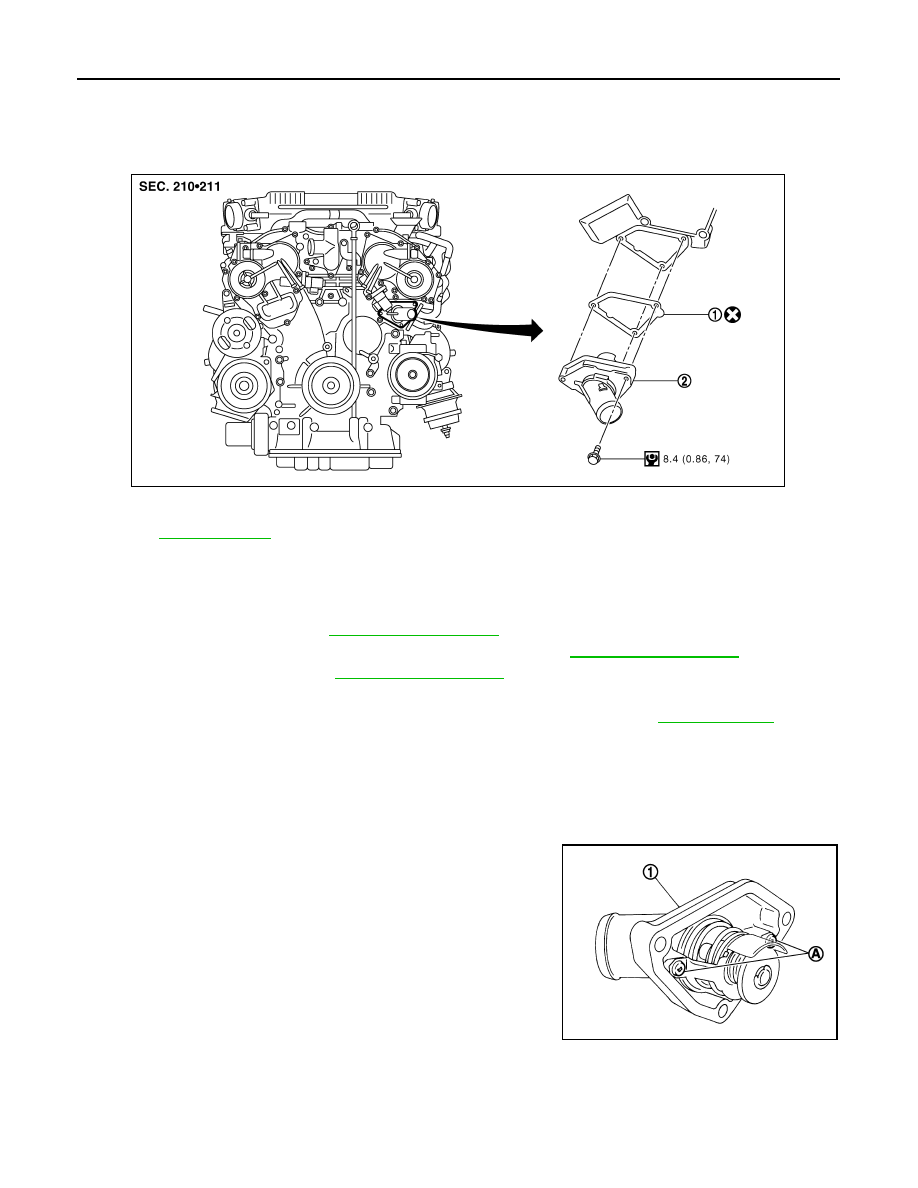
8.
Remove water inlet and thermostat assembly (1).
CAUTION:
Never disassemble water inlet and thermostat assembly.
Replace them as a unit, if necessary.
INSTALLATION
Note the following, and install in the reverse order of removal.
• Be careful not to spill engine coolant over engine room. Use rag to absorb engine coolant.
1.
Gasket
2.
Water inlet and thermostat assembly
Refer to
for symbols in the figure.
JPBIA1466GB
A
: Never loosen these screws.
JPBIA0261ZZ

WATER INLET AND THERMOSTAT ASSEMBLY
CO-23
< REMOVAL AND INSTALLATION >
[VQ35HR]
C
D
E
F
G
H
I
J
K
L
M
A
CO
N
P
O
Inspection
INFOID:0000000005246372
INSPECTION AFTER REMOVAL
1.
Check valve seating condition at ordinary room temperatures. It should seat tightly.
2.
Check valve operation.
• If the malfunctioning condition, when valve seating at ordinary
room temperature, or measured values are out of the standard,
replace water inlet and thermostat assembly.
INSPECTION AFTER INSTALLATION
• Check that the reservoir tank cap is tightened.
• Check for leakage of engine coolant using the radiator cap tester adapter (commercial service tool) and the
radiator cap tester (commercial service tool). Refer to
.
• Start and warm up the engine. Visually check that there is no leakage of engine coolant.
Thermostat (Standard)
: Refer to
.
SLC949A
CO-24
< REMOVAL AND INSTALLATION >
[VQ35HR]
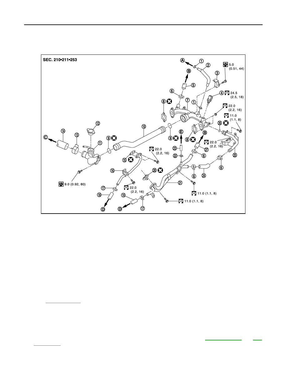
WATER OUTLET AND WATER PIPING
WATER OUTLET AND WATER PIPING
Exploded View
INFOID:0000000005246373
Removal and Installation
INFOID:0000000005246374
REMOVAL
1.
Remove engine undercover with a power tool.
2.
Drain engine coolant from drain plugs on radiator and cylinder block. Refer to
.
CAUTION:
• Perform this step when the engine is cold.
1.
Clamp
2.
Water hose
3.
Harness bracket
4.
Engine coolant temperature sensor
5.
Heater hose
6.
Clamp
7.
Water outlet (rear)
8.
Gasket
9.
O-ring
10. Water outlet pipe
11.
Water outlet (front)
12.
Radiator cap
13. Clamp
14.
Radiator hose (upper)
15.
Gasket
16. Water pipe
17.
Clamp
18.
Water hose
19. Water hose
20.
Gasket
21.
Heater pipe
22. Clamp
23.
Water hose
24.
Water hose
25. Water bypass pipe
26.
O-ring
27.
Heater hose
A.
To electric throttle control actuator
(bank 1)
B.
To heater core
C.
To radiator
D.
To oil cooler
E.
To electric throttle control actuator
(bank 2)
Refer to
for symbols in the figure.
JPBIA2319GB
Нет комментариевНе стесняйтесь поделиться с нами вашим ценным мнением.
Текст