Infiniti FX35, FX50 (S51). Manual — part 443
COOLING FAN
CO-17
< REMOVAL AND INSTALLATION >
[VQ35HR]
C
D
E
F
G
H
I
J
K
L
M
A
CO
N
P
O
COOLING FAN
Exploded View
INFOID:0000000005246363
Removal and Installation
INFOID:0000000005246364
REMOVAL
1.
Drain engine coolant. Refer to
2.
Remove reservoir tank. Refer to
.
3.
Remove air cleaner case (bank 1 and bank 2). Refer to
.
4.
Remove mounting bolt from high pressure flexible hose bracket. Refer to
5.
Remove radiator hose (upper). Refer to
.
6.
Disconnect harness connector from cooling fan control module, and move harness to aside.
7.
Remove cooling fan assembly.
CAUTION:
Be careful not to damage or scratch on radiator core.
INSTALLATION
Note the following, and install in the reverse order of removal.
CAUTION:
Only use genuine parts for cooling fan mounting bolt and observe the specified torque (to prevent
radiator from being damaged).
Disassembly and Assembly
INFOID:0000000005246365
DISASSEMBLY
1.
Disconnect harness connector from cooling fan control module.
2.
Remove cooling fan control module from cooling fan assembly.
CAUTION:
Handle carefully to avoid dropping and impact.
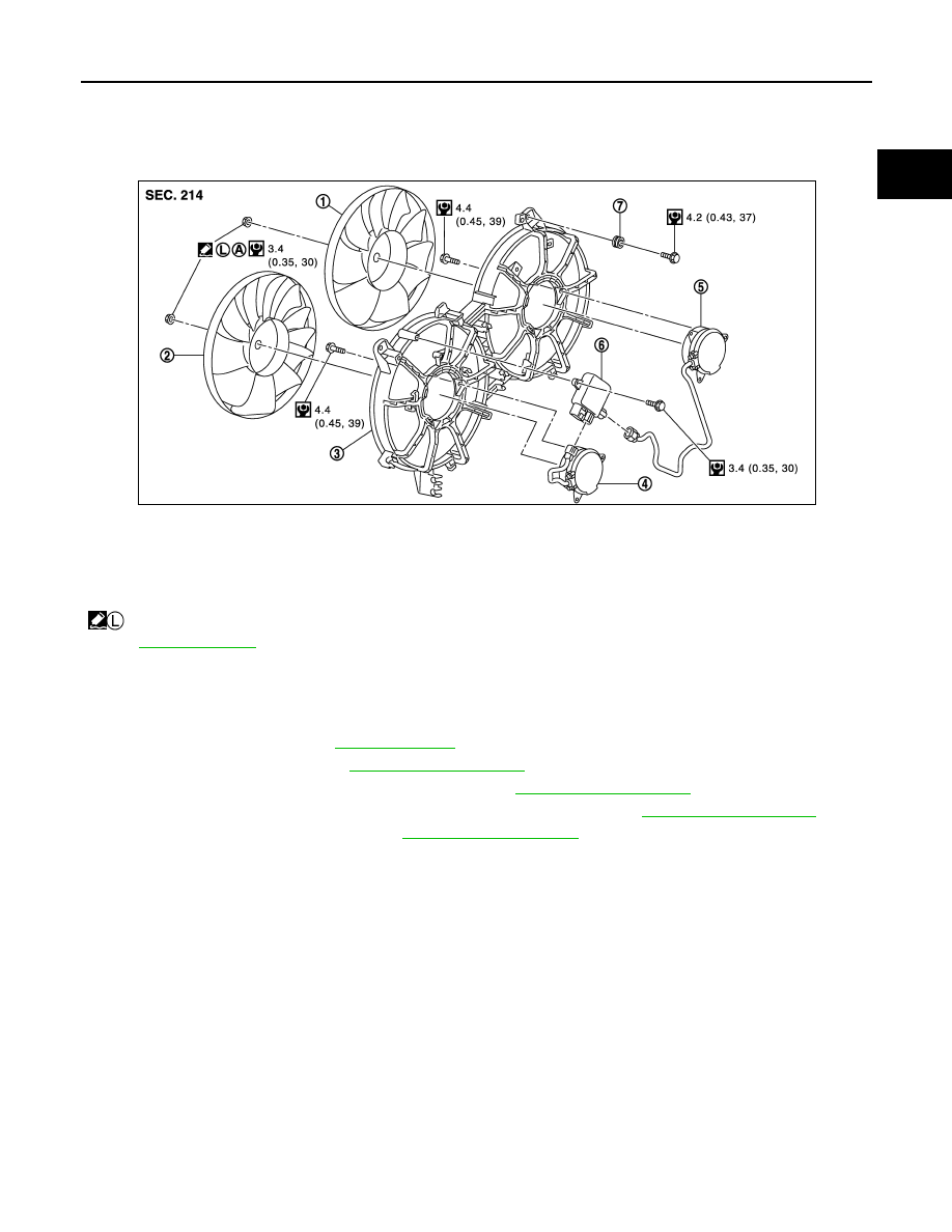
1.
Cooling fan (RH)
2.
Cooling fan (LH)
3.
Fan shroud
4.
Fan motor (LH)
5.
Fan motor (RH)
6.
Cooling fan control module
7.
Grommet
A.
Apply on fan motor shaft
: Apply high strength thread locking sealant or equivalent.
for symbols not described on the above.
JPBIA1833GB
CO-18
< REMOVAL AND INSTALLATION >
[VQ35HR]
COOLING FAN
3.
Remove cooling fan mounting nuts, and then remove the cooling fan (RH and LH).
4.
Remove fan motors (RH and LH).
ASSEMBLY
Note the following, and assemble in the reverse order of disassembly.
CAUTION:
RH and LH cooling fans are different. Be careful not to misassemble them.
• Install each fan in the following position.
• Secure the harness tightly to the fan shroud to prevent the fan rotation area from being slack.
Inspection
INFOID:0000000005246366
INSPECTION AFTER REMOVAL
Check that fan motors operate normally.
NOTE:
Cooling fans are controlled by cooling fan control module. For details, refer to
INSPECTION AFTER DISASSEMBLY
Cooling Fan
Inspect cooling fan for crack or unusual bend.
• If anything is found, replace cooling fan.
Right side
: 9 blades
Left side
: 11 blades
WATER PUMP
CO-19
< REMOVAL AND INSTALLATION >
[VQ35HR]
C
D
E
F
G
H
I
J
K
L
M
A
CO
N
P
O
WATER PUMP
Exploded View
INFOID:0000000005246367
Removal and Installation
INFOID:0000000005550802
CAUTION:
• When removing water pump assembly, be careful not to get engine coolant on drive belt.
• Water pump cannot be disassembled and should be replaced as a unit.
• After installing water pump, connect hose and clamp securely, then check for leakage using the radi-
ator cap tester (commercial service tool) and the radiator cap tester adapter (commercial service
tool).
REMOVAL
1.
Remove engine cover. Refer to
.
2.
Release the fuel pressure. Refer to
.
3.
Disconnect the battery cable from the negative terminal.
4.
Remove air duct and air cleaner case assembly (bank 1 and bank 2). Refer to
.
5.
Remove reservoir tank. Refer to
.
6.
Separate engine harness removing their brackets from front timing chain case.
7.
Remove engine undercover with a power tool.
8.
Drain engine oil. Refer to
.
CAUTION:
• Perform this step when the engine is cold.
• Never spill engine oil on drive belt.
9.
Drain engine coolant from radiator. Refer to
.
CAUTION:
• Perform this step when the engine is cold.
• Never spill engine coolant on drive belt.
10. Remove radiator hose (lower). Refer to
.
11. Remove cooling fan assembly. Refer to
12. Remove front timing chain case. Refer to
.
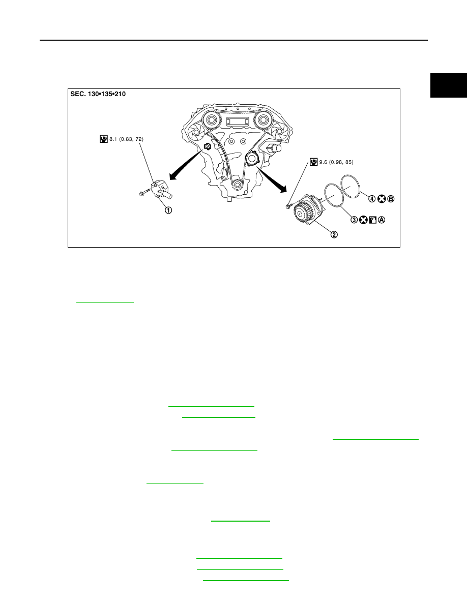
1.
Timing chain tensioner (primary)
2.
Water pump
3.
O-ring
4.
O-ring
A.
Identify with yellow paint mark
B.
Identify with light blue paint mark
Apply engine coolant
Refer to
JPBIA0270GB

CO-20
< REMOVAL AND INSTALLATION >
[VQ35HR]
WATER PUMP
13. Remove timing chain tensioner (primary) as per the following:
a.
Remove lower mounting bolt (A).
b.
Loosen upper mounting bolt (B) slowly, and then turn chain ten-
sioner (primary) (1) on the upper mounting bolt so that plunger
(C) is fully expanded.
NOTE:
Even if plunger is fully expanded, it is not dropped from the body
of timing chain tensioner (primary).
c.
Remove upper mounting bolt, and then remove timing chain tensioner (primary).
14. Remove water pump as per the following:
a.
Remove three water pump mounting bolts. Secure a gap between water pump gear and timing chain, by
turning crankshaft counterclockwise until timing chain looseness on water pump sprocket becomes maxi-
mum.
b.
Screw M8 bolts (A) [pitch: 1.25 mm (0.0492 in) length: approxi-
mately 50 mm (1.97 in)] into water pumps upper and lower
mounting bolt holes until they reach timing chain case. Then,
alternately tighten each bolt for a half turn, and pull out water
pump (1).
CAUTION:
• Pull straight out while preventing vane from contacting
socket in installation area.
• Remove water pump without causing sprocket to contact
timing chain.
c.
Remove M8 bolts and O-rings from water pump.
CAUTION:
Never disassemble water pump.
INSTALLATION
1.
Install new O-rings to water pump.
• Apply engine oil to O-ring (1) and engine coolant to O-ring (3)
as shown in the figure.
• Locate O-ring with yellow paint mark (A) to front side.
• Locate O-ring with light blue paint mark (B) to rear side.
2.
Install water pump.
CAUTION:
Never allow cylinder block to nip O-rings when installing water pump.
• Check timing chain and water pump sprocket are engaged.
• Insert water pump by tightening mounting bolts alternately and evenly.
3.
Install timing chain tensioner (primary) as per the following:
a.
Turn crankshaft clockwise so that timing chain on the timing chain tensioner (primary) side is loose.
JPBIA1537ZZ
JPBIA0111ZZ
2
: Water pump
JPBIA0112ZZ
Нет комментариевНе стесняйтесь поделиться с нами вашим ценным мнением.
Текст