Infiniti FX35, FX50 (S51). Manual — part 826
P0172, P0175 FUEL INJECTION SYSTEM FUNCTION
EC-845
< DTC/CIRCUIT DIAGNOSIS >
[VK50VE]
C
D
E
F
G
H
I
J
K
L
M
A
EC
N
P
O
5.
PERFORM DTC CONFIRMATION PROCEDURE-III
1.
Turn ignition switch OFF and wait at least 10 seconds.
2.
Turn ignition switch ON.
3.
Turn ignition switch OFF and wait at least 10 seconds.
4.
Start engine.
5.
Maintain the following conditions for at least 10 consecutive minutes.
Hold the accelerator pedal as steady as possible.
CAUTION:
Always drive vehicle at a safe speed.
6.
Check 1st trip DTC.
Is 1st trip DTC detected?
YES
>> Go to
NO
>> INSPECTION END
Diagnosis Procedure
INFOID:0000000005237322
1.
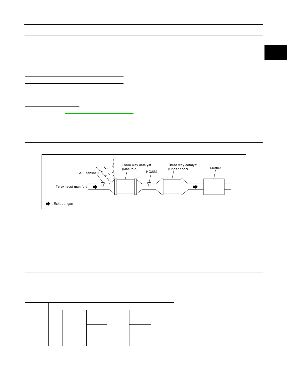
CHECK EXHAUST GAS LEAKAGE
1.
Start engine and run it at idle.
2.
Listen for an exhaust gas leakage before three way catalyst (manifold).
Is exhaust gas leakage detected?
YES
>> Repair or replace malfunctioning part.
NO
>> GO TO 2.
2.
CHECK FOR INTAKE AIR LEAKAGE
Listen for an intake air leakage after the mass air flow sensor.
Is intake air leakage detected?
YES
>> Repair or replace malfunctioning part.
NO
>> GO TO 3.
3.
CHECK A/F SENSOR 1 INPUT SIGNAL CIRCUIT
1.
Turn ignition switch OFF.
2.
Disconnect corresponding A/F sensor 1 harness connector.
3.
Disconnect ECM harness connector.
4.
Check the continuity between A/F sensor 1 harness connector and ECM harness connector.
5.
Check the continuity between A/F sensor 1 harness connector and ground, or ECM harness connector
and ground.
Vehicle speed
50 - 120 km/h (31 - 75 MPH)
PBIB1216E
DTC
A/F sensor 1
ECM
Continuity
Bank
Connector
Terminal
Connector
Terminal
P0172
1
F67
1
F111
81
Existed
2
82
P0175
2
F68
1
85
2
86
EC-846
< DTC/CIRCUIT DIAGNOSIS >
[VK50VE]
P0172, P0175 FUEL INJECTION SYSTEM FUNCTION
6.
Also check harness for short to power.
Is the inspection result normal?
YES
>> GO TO 4.
NO
>> Repair open circuit, short to ground or short to power in harness or connectors.
4.
CHECK FUEL PRESSURE
Check fuel pressure. Refer to
.
Is the inspection result normal?
YES
>> GO TO 5.
NO
>> Replace “fuel filter and fuel pump assembly”.
5.
CHECK MASS AIR FLOW SENSOR
With CONSULT-III
1.
Install all removed parts.
2.
Check “MASS AIR FLOW” in “DATA MONITOR” mode with CONSULT-III.
For specification, refer to
EC-1241, "Mass Air Flow Sensor"
With GST
1.
Install all removed parts.
2.
Check mass air flow sensor signal in “Service $01” with GST.
For specification, refer to
EC-1241, "Mass Air Flow Sensor"
Is the measurement value within the specification?
YES
>> GO TO 6.
NO
>> Check connectors for rusted terminals or loose connections in the mass air flow sensor circuit or
grounds. Refer to
6.
CHECK FUNCTION OF FUEL INJECTOR
With CONSULT-III
1.
Start engine.
2.
Perform “POWER BALANCE” in “ACTIVE TEST” mode with CONSULT-III.
3.
Check that each circuit produces a momentary engine speed drop.
Without CONSULT-III
1.
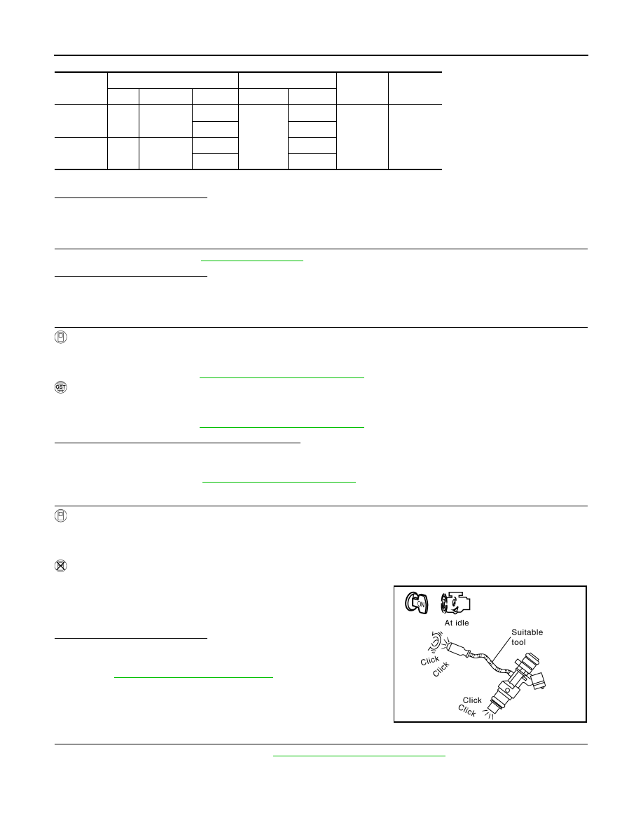
Start engine and let it idle.
2.
Listen to each fuel injector operating sound.
Is the inspection result normal?
YES
>> GO TO 7.
NO
>> Perform trouble diagnosis for FUEL INJECTOR, refer to
EC-1103, "Diagnosis Procedure"
7.
CHECK FUEL INJECTOR
1.
Remove fuel injector assembly. Refer to
EM-182, "Removal and Installation"
.
Keep fuel hose and all fuel injectors connected to fuel tube.
2.
Confirm that the engine is cooled down and there are no fire hazards near the vehicle.
3.
Disconnect all fuel injector harness connectors.
DTC
A/F sensor 1
ECM
Ground
Continuity
Bank
Connector
Terminal
Connector
Terminal
P0172
1
F67
1
F111
81
Ground
Not existed
2
82
P0175
2
F68
1
85
2
86
Clicking sound should be heard.
PBIB3332E

P0172, P0175 FUEL INJECTION SYSTEM FUNCTION
EC-847
< DTC/CIRCUIT DIAGNOSIS >
[VK50VE]
C
D
E
F
G
H
I
J
K
L
M
A
EC
N
P
O
4.
Disconnect all ignition coil harness connectors.
5.
Prepare pans or saucers under each fuel injector.
6.
Crank engine for approximately 3 seconds.
Check that fuel does not drip from fuel injector.
Is the inspection result normal?
YES
>> GO TO 8.
NO
>> Replace the fuel injectors from which fuel is dripping. Always replace O-ring with new one.
8.
CHECK INTERMITTENT INCIDENT
GI-36, "Intermittent Incident"
.
>> INSPECTION END
EC-848
< DTC/CIRCUIT DIAGNOSIS >
[VK50VE]
P0181 FTT SENSOR
P0181 FTT SENSOR
Description
INFOID:0000000005237323
The fuel tank temperature sensor is used to detect the fuel tempera-
ture inside the fuel tank. The sensor modifies a voltage signal from
the ECM. The modified signal returns to the ECM as the fuel temper-
ature input. The sensor uses a thermistor which is sensitive to the
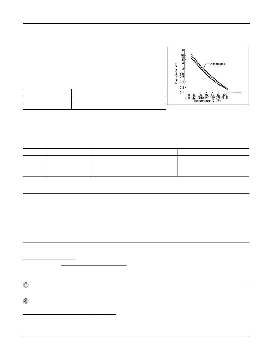
change in temperature. The electrical resistance of the thermistor
decreases as temperature increases.
<Reference data>
*: These data are reference values and are measured between ECM terminals 120 (Fuel tank temperature sensor) and 128 (ECM
ground).
DTC Logic
INFOID:0000000005237324
DTC DETECTION LOGIC
DTC CONFIRMATION PROCEDURE
1.
PRECONDITIONING
If DTC Confirmation Procedure has been previously conducted, always perform the following procedure
before conducting the next test.
1.
Turn ignition switch OFF and wait at least 10 seconds.
2.
Turn ignition switch ON.
3.
Turn ignition switch OFF and wait at least 10 seconds.
>> GO TO 2.
2.
PERFORM DTC CONFIRMATION PROCEDURE-I
1.
Turn ignition switch ON and wait at least 10 seconds.
2.
Check 1st trip DTC.
Is 1st trip DTC detected?
YES
>> Go to
NO
>> GO TO 3.
3.
CHECK ENGINE COOLANT TEMPERATURE
With CONSULT-III
1.
Select “COOLAN TEMP/S” in “DATA MONITOR” with CONSULT-III.
2.
Check “COOLAN TEMP/S” value.
With GST
Follow the procedure “With CONSULT-III” above.
“COOLAN TEMP/S” less than 60
°
C (140
°
F)?
YES
>> INSPECTION END
NO
>> GO TO 4.
4.
PERFORM DTC CONFIRMATION PROCEDURE-II
Fuel temperature [
°
C (
°
F)]
Voltage* (V)
Resistance (k
Ω
)
20 (68)
3.5
2.3 - 2.7
50 (122)
2.2
0.79 - 0.90
SEF012P
DTC No.
Trouble diagnosis name
DTC detecting condition
Possible cause
P0181
Fuel tank temperature
sensor circuit range/
performance
Rationally incorrect voltage from the sensor is sent
to ECM, compared with the voltage signals from
engine coolant temperature sensor and intake air
temperature sensor.
• Harness or connectors
(The sensor circuit is open or shorted)
• Fuel tank temperature sensor
• Unified meter and A/C amp.
Нет комментариевНе стесняйтесь поделиться с нами вашим ценным мнением.
Текст