Infiniti FX35, FX50 (S51). Manual — part 1885

A/T FLUID COOLER
TM-347
< PERIODIC MAINTENANCE >
[7AT: RE7R01B (VK50VE)]
C
E
F
G
H
I
J
K
L
M
A
B
TM
N
O
P
b.
If one or more pieces of debris are found that are over 1 mm
(0.040 in) in size and/or peeled clutch facing material is found in
the coffee filter, the A/T fluid cooler is not serviceable. The A/T
fluid cooler/radiator must be replaced and the inspection proce-
dure is ended. Refer to
Inspection
INFOID:0000000005250345
After performing all procedures, ensure that all remaining oil is cleaned from all components.
SCIA7031E

TM-348
< PERIODIC MAINTENANCE >
[7AT: RE7R01B (VK50VE)]
STALL TEST
STALL TEST
Inspection and Judgment
INFOID:0000000005250346
INSPECTION
1.
Inspect the amount of engine oil. Replenish the engine oil if necessary.
2.
Drive for about 10 minutes to warm up the vehicle so that the A/T fluid temperature is 50 to 80
°
C (122 to
176
°
F). Inspect the amount of ATF. Replenish if necessary.
3.
Securely engage the parking brake so that the tires do not turn.
4.
Start the engine, apply foot brake, and place selector lever in “D” position.
5.
Gradually press down the accelerator pedal while holding down the foot brake.
6.
Quickly read off the stall speed, and then quickly release the accelerator pedal.
CAUTION:
Never hold down the accelerator pedal for more than 5 seconds during this test.
7.
Shift the selector lever to “N” position.
8.
Cool down the ATF.
CAUTION:
Run the engine at idle for at least 1 minute.
9.
Repeat steps 5 through 8 with selector lever in “R” position.
JUDGMENT OF STALL TEST
O: Stall speed within standard value position
H: Stall speed higher than standard value
L: Stall speed lower than standard value
Stall test standard value position
Stall speed
: Refer to
Selector lever position
Possible location of malfunction
“D” and “M”
“R”
Stall speed
H
O
• Low brake
• 1st one-way clutch
• 2nd one-way clutch
O
H
• Reverse brake
• 1st one-way clutch
• 2nd one-way clutch
L
L
• Engine and torque converter one-way clutch
H
H
• Line pressure low
Does not shift-up “D” or “M” position 1
→
2
Slipping in 2GR, 3GR 4GR or 6GR
2346 brake slippage
Does not shift-up “D” or “M” position 2
→
3
Slipping in 3GR, 4GR or 5GR
Direct clutch slippage
Does not shift-up “D” or “M” position 3
→
4
Slipping in 4GR, 5GR, 6GR or 7GR
High and low reverse clutch slippage
Does not shift-up “D” or “M” position 4
→
5
Slipping in 5GR, 6GR or 7GR
Input clutch slippage
Does not shift-up “D” or “M” position 5
→
6
Slipping in 2GR, 3GR, 4GR or 6GR
2346 brake slippage
Does not shift-up “D” or “M” position 6
→
7
Slipping in 7GR
Front brake slippage
A/T POSITION
TM-349
< PERIODIC MAINTENANCE >
[7AT: RE7R01B (VK50VE)]
C
E
F
G
H
I
J
K
L
M
A
B
TM
N
O
P
A/T POSITION
Inspection and Adjustment
INFOID:0000000005250347
INSPECTION
1.
Place selector lever in “P” position, and turn ignition switch ON (engine stop).
2.
Check that selector lever can be shifted to other than “P” position when brake pedal is depressed. Also
check that selector lever can be shifted from “P” position only when brake pedal is depressed.
3.
Shift the selector lever and check for excessive effort, sticking, noise or rattle.
4.
Confirm that the selector lever stops at each position by feeling the engagement when it is moved through
all the positions. Check whether or not the actual position the selector lever matches the position shown
by the shift position indicator and the A/T body.
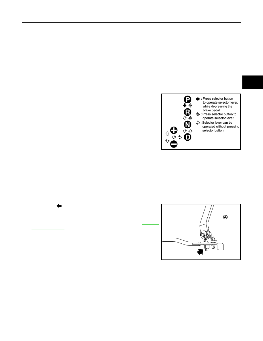
5.
The method of operating the lever to individual positions cor-
rectly is shown in the figure.
6.
When selector button is pressed in “P”, “R”, or “N” position with-
out applying forward/backward force to selector lever, check but-
ton operation for sticking.
7.
Confirm that the back-up lamps illuminate only when lever is
placed in the “R” position. Confirm that the back-up lamps do not
illuminate when selector lever is pushed against “R” position in
the “P” or “N” position.
8.
Confirm that the engine can only be started with the selector
lever in the “P” and “N” positions. (With selector lever in the “P”
position, engine can be started even when selector lever is
moved forward and backward.)
9.
Make sure that A/T is locked completely in “P” position.
10. DS mode must be indicated on the combination meter when the selector lever is shifted to the manual
shift gate. When the selector lever is shifted to the “+” or “
−
” side in the DS mode, manual mode should be
indicated on the combination meter.
In addition, a set shift position must be changed when the selector lever is shifted to the “+” or “
−
” side in
the manual mode. (Only while driving.)
ADJUSTMENT
1.
Loosen nut (
).
2.
Place manual lever and selector lever in “P” position.
3.
While pressing lower lever (A) toward rear of vehicle (in “P” posi-
tion direction), tighten nut to specified torque. Refer to
CAUTION:
Be careful not to touch the control rod while pressing lower
lever of A/T shift selector assembly.
NOTE:
Press lower lever of A/T shift selector assembly with a force of
approximately 1 kg (9.8 N).
JSDIA0790GB
JPDIA0884ZZ
TM-350
< REMOVAL AND INSTALLATION >
[7AT: RE7R01B (VK50VE)]
A/T SHIFT SELECTOR
REMOVAL AND INSTALLATION
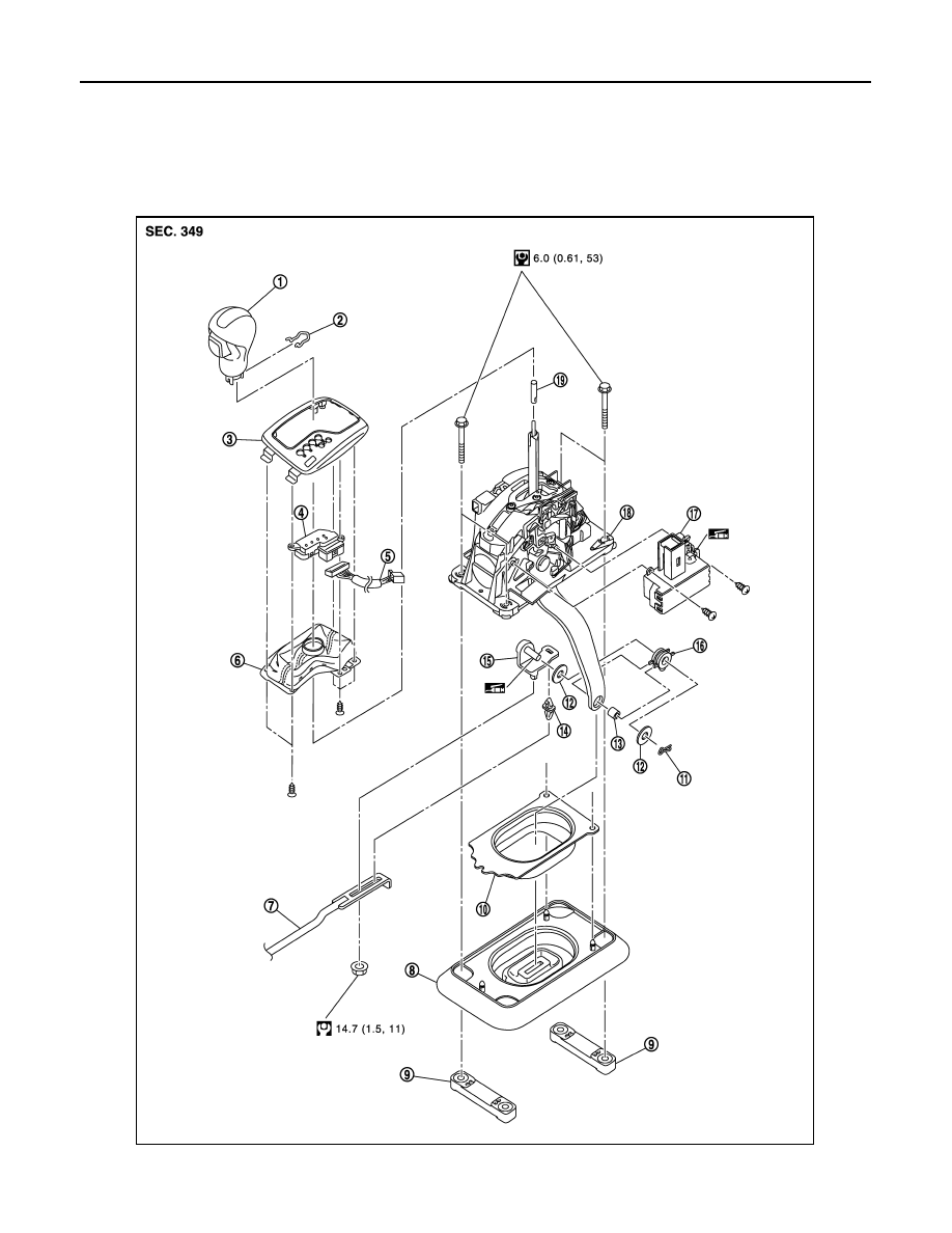
A/T SHIFT SELECTOR
Exploded View
INFOID:0000000005250348
JSDIA1353GB
Нет комментариевНе стесняйтесь поделиться с нами вашим ценным мнением.
Текст