Infiniti FX35, FX50 (S51). Manual — part 1279
LAN-58
< DTC/CIRCUIT DIAGNOSIS >
[CAN]
MALFUNCTION AREA CHART
MALFUNCTION AREA CHART
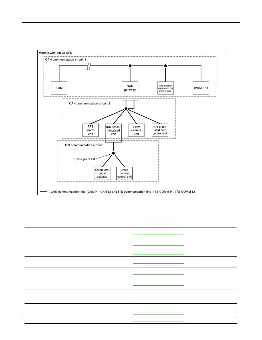
System Diagram
INFOID:0000000005241893
CAN Communication Circuit
INFOID:0000000005241894
MAIN LINE
BRANCH LINE
JSMIA0144GB
Malfunction area
Reference
Main line between data link connector and unified meter and A/C
amp.
Main line between unified meter and A/C amp. and driver seat
control unit
Main line between driver seat control unit and CAN gateway
Main line between CAN gateway and ABS actuator and electric
unit (control unit)
Main line between unified meter and A/C amp. and ABS actuator
and electric unit (control unit)
Main line between driver seat control unit and ABS actuator and
electric unit (control unit)
Malfunction area
Reference
ECM branch line circuit
AWD control unit branch line circuit
LAN
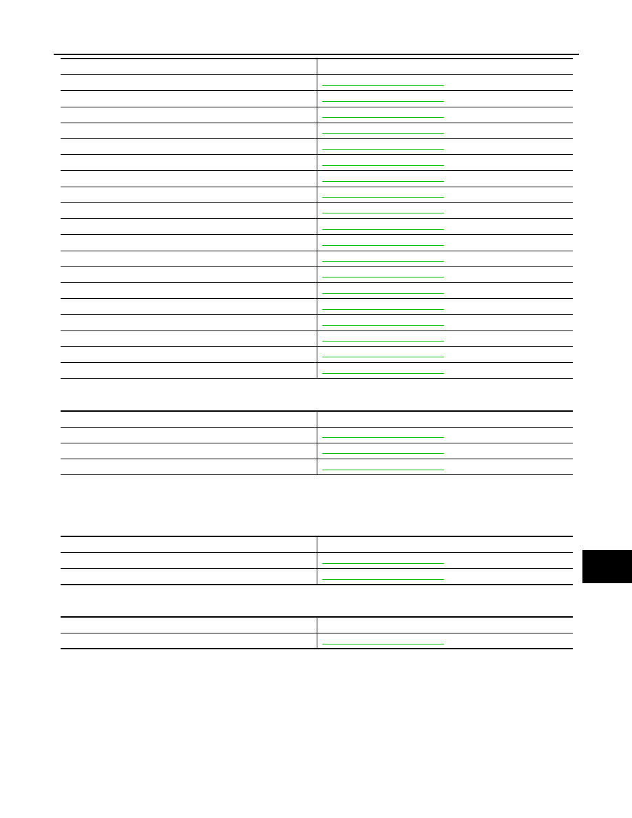
MALFUNCTION AREA CHART
LAN-59
< DTC/CIRCUIT DIAGNOSIS >
[CAN]
C
D
E
F
G
H
I
J
K
L
B
A
O
P
N
SHORT CIRCUIT
ITS Communication Circuit
INFOID:0000000005241895
BRANCH LINE
SHORT CIRCUIT OR OPEN CIRCUIT
Data link connector branch line circuit
TCM branch line circuit
Air bag diagnosis sensor unit branch line circuit
AV control unit branch line circuit
BCM branch line circuit
Unified meter and A/C amp. branch line circuit
Steering angle sensor branch line circuit
Low tire pressure warning control unit branch line circuit
Driver seat control unit branch line circuit
E-SUS control unit branch line circuit
RAS control unit branch line circuit
CAN gateway branch line circuit (CAN communication circuit 1)
CAN gateway branch line circuit (CAN communication circuit 2)
ABS actuator and electric unit (control unit) branch line circuit
IPDM E/R branch line circuit
AFS control unit branch line circuit
ICC sensor integrated unit branch line circuit
Lane camera unit branch line circuit
Pre-crash seat belt control unit branch line circuit
Malfunction area
Reference
Malfunction area
Reference
CAN communication circuit
CAN communication circuit 1
CAN communication circuit 2
Malfunction area
Reference
Accelerator pedal actuator branch line circuit
Brake booster control unit branch line circuit
Malfunction area
Reference
ITS communication circuit

LAN-60
< DTC/CIRCUIT DIAGNOSIS >
[CAN]
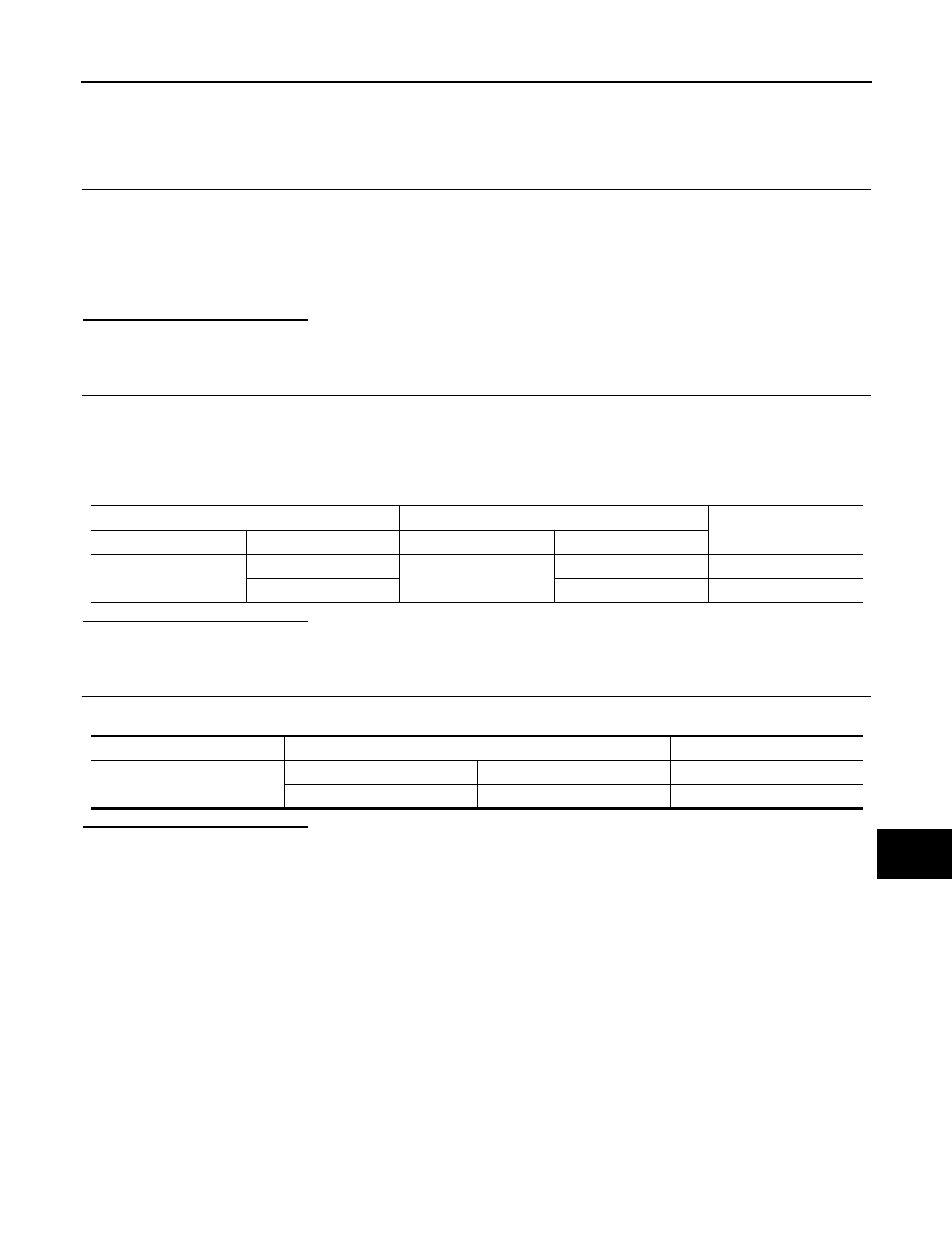
MAIN LINE BETWEEN DLC AND M&A CIRCUIT
MAIN LINE BETWEEN DLC AND M&A CIRCUIT
Diagnosis Procedure
INFOID:0000000005241896
1.
CHECK HARNESS CONTINUITY (OPEN CIRCUIT)
1.
Turn the ignition switch OFF.
2.
Disconnect the battery cable from the negative terminal.
3.
Disconnect the following harness connectors.
-
ECM
-
Unified meter and A/C amp.
4.
Check the continuity between the data link connector and the unified meter and A/C amp. harness con-
nector.
Is the inspection result normal?
YES (Present error)>>Check CAN system type decision again.
YES (Past error)>>Error was detected in the main line between the data link connector and the unified meter
and A/C amp.
NO
>> Repair the main line between the data link connector and the unified meter and A/C amp.
Data link connector
Unified meter and A/C amp. harness connector
Continuity
Connector No.
Terminal No.
Connector No.
Terminal No.
M24
6
M67
56
Existed
14
72
Existed
LAN
MAIN LINE BETWEEN M&A AND ADP CIRCUIT
LAN-61
< DTC/CIRCUIT DIAGNOSIS >
[CAN]
C
D
E
F
G
H
I
J
K
L
B
A
O
P
N
MAIN LINE BETWEEN M&A AND ADP CIRCUIT
Diagnosis Procedure
INFOID:0000000005241897
1.
CHECK CONNECTOR
1.
Turn the ignition switch OFF.
2.
Disconnect the battery cable from the negative terminal.
3.
Check the following terminals and connectors for damage, bend and loose connection (connector side
and harness side).
-
Harness connector M7
-
Harness connector B1
Is the inspection result normal?
YES
>> GO TO 2.
NO
>> Repair the terminal and connector.
2.
CHECK HARNESS CONTINUITY (OPEN CIRCUIT)
1.
Disconnect the following harness connectors.
-
Unified meter and A/C amp.
-
Harness connectors M7 and B1
2.
Check the continuity between the unified meter and A/C amp. harness connector and the harness con-
nector.
Is the inspection result normal?
YES
>> GO TO 3.
NO
>> Repair the main line between the unified meter and A/C amp. and the harness connector M7.
3.
CHECK HARNESS CONTINUITY (OPEN CIRCUIT)
Check the continuity between the harness connector terminals.
Is the inspection result normal?
YES (Present error)>>Check CAN system type decision again.
YES (Past error)>>Error was detected in the main line between the unified meter and A/C amp. and the
driver seat control unit.
NO
>> Repair the main line between the harness connector B1 and the driver seat control unit.
Unified meter and A/C amp. harness connector
Harness connector
Continuity
Connector No.
Terminal No.
Connector No.
Terminal No.
M67
56
M7
80
Existed
72
81
Existed
Connector No.
Terminal No.
Continuity
B1
80
82
Existed
81
83
Existed
Нет комментариевНе стесняйтесь поделиться с нами вашим ценным мнением.
Текст