Infiniti FX35, FX50 (S51). Manual — part 831
P0300, P0301, P0302, P0303, P0304, P0305, P0306, P0307, P0308 MISFIRE
EC-865
< DTC/CIRCUIT DIAGNOSIS >
[VK50VE]
C
D
E
F
G
H
I
J
K
L
M
A
EC
N
P
O
5.
Restart engine and let it idle for about 15 minutes.
6.
Check 1st trip DTC.
Is 1st trip DTC detected?
YES
>> Go to
NO
>> GO TO 3.
3.
PERFORM DTC CONFIRMATION PROCEDURE-II
1.
Turn ignition switch OFF and wait at least 10 seconds.
2.
Turn ignition switch ON.
3.
Turn ignition switch OFF and wait at least 10 seconds.
4.
Start engine and drive the vehicle under similar conditions to (1st trip) Freeze Frame Data for a certain
time. Refer to the table below.
Hold the accelerator pedal as steady as possible.
Similar conditions to (1st trip) Freeze Frame Data mean that the following conditions should be satisfied at
the same time.
CAUTION:
Always drive vehicle in safe manner according to traffic conditions and obey all traffic laws when
driving.
Driving time varies according to the engine speed in the freeze frame data.
5.
Check 1st trip DTC.
Is 1st trip DTC detected?
YES
>> Go to
NO
>> INSPECTION END
Diagnosis Procedure
INFOID:0000000005237346
1.
CHECK FOR INTAKE AIR LEAKAGE AND PCV HOSE
1.
Start engine and run it at idle speed.
2.
Listen for the sound of the intake air leakage.
3.
Check PCV hose connection.
Is intake air leakage detected?
YES
>> Discover air leakage location and repair.
NO
>> GO TO 2.
2.
CHECK FOR EXHAUST SYSTEM CLOGGING
Stop engine and visually check exhaust tube, three way catalyst and muffler for dents.
Is the inspection result normal?
YES-1 >> With CONSULT-III: GO TO 3.
YES-2 >> Without CONSULT-III: GO TO 4.
NO
>> Repair or replace malfunctioning part.
3.
PERFORM POWER BALANCE TEST
Engine speed
Engine speed in the freeze frame data
±
400 rpm
Vehicle speed
Vehicle speed in the freeze frame data
±
10 km/h (6 MPH)
Base fuel schedule
Base fuel schedule in the freeze frame data
×
(1
±
0.1)
Engine coolant temperature (T)
condition
When the freeze frame data shows lower than 70
°
C (158
°
F),
T should be lower than 70
°
C (158
°
F).
When the freeze frame data shows higher than or equal to 70
°
C (158
°
F),
T should be higher than or equal to 70
°
C (158
°
F).
Engine speed
Time
Around 1,000 rpm
Approximately 10 minutes
Around 2,000 rpm
Approximately 5 minutes
More than 3,000 rpm
Approximately 3.5 minutes

EC-866
< DTC/CIRCUIT DIAGNOSIS >
[VK50VE]
P0300, P0301, P0302, P0303, P0304, P0305, P0306, P0307, P0308 MISFIRE
With CONSULT-III
1.
Start engine.
2.
Perform “POWER BALANCE” in “ACTIVE TEST” mode with CONSULT-III.
3.
Check that each circuit produces a momentary engine speed drop.
Is the inspection result normal?
YES
>> GO TO 9.
NO
>> GO TO 4.
4.
CHECK FUNCTION OF FUEL INJECTOR-I
1.
Start engine and let it idle.
2.
Listen to each fuel injector operation.
Is the inspection result normal?
YES
>> GO TO 5.
NO
>> Perform trouble diagnosis for FUEL INJECTOR, refer to
EC-1103, "Diagnosis Procedure"
5.
CHECK FUNCTION OF IGNITION COIL-I
CAUTION:
Perform the following procedure in a place with no combustible objects and good ventilation.
1.
Turn ignition switch OFF.
2.
Remove fuel pump fuse (1) in IPDM E/R (2) to release fuel pres-
sure.
NOTE:
Do not use CONSULT-III to release fuel pressure, or fuel pres-
sure applies again during the following procedure.
3.
Start engine.
4.
After engine stalls, crank it 2 or 3 times to release all fuel pres-
sure.
5.
Turn ignition switch OFF.
6.
Remove all ignition coil harness connectors to avoid the electri-
cal discharge from the ignition coils.
7.
Remove ignition coil and spark plug of the cylinder to be
checked.
8.
Crank engine for 5 seconds or more to remove combustion gas in the cylinder.
9.
Connect spark plug and harness connector to ignition coil.
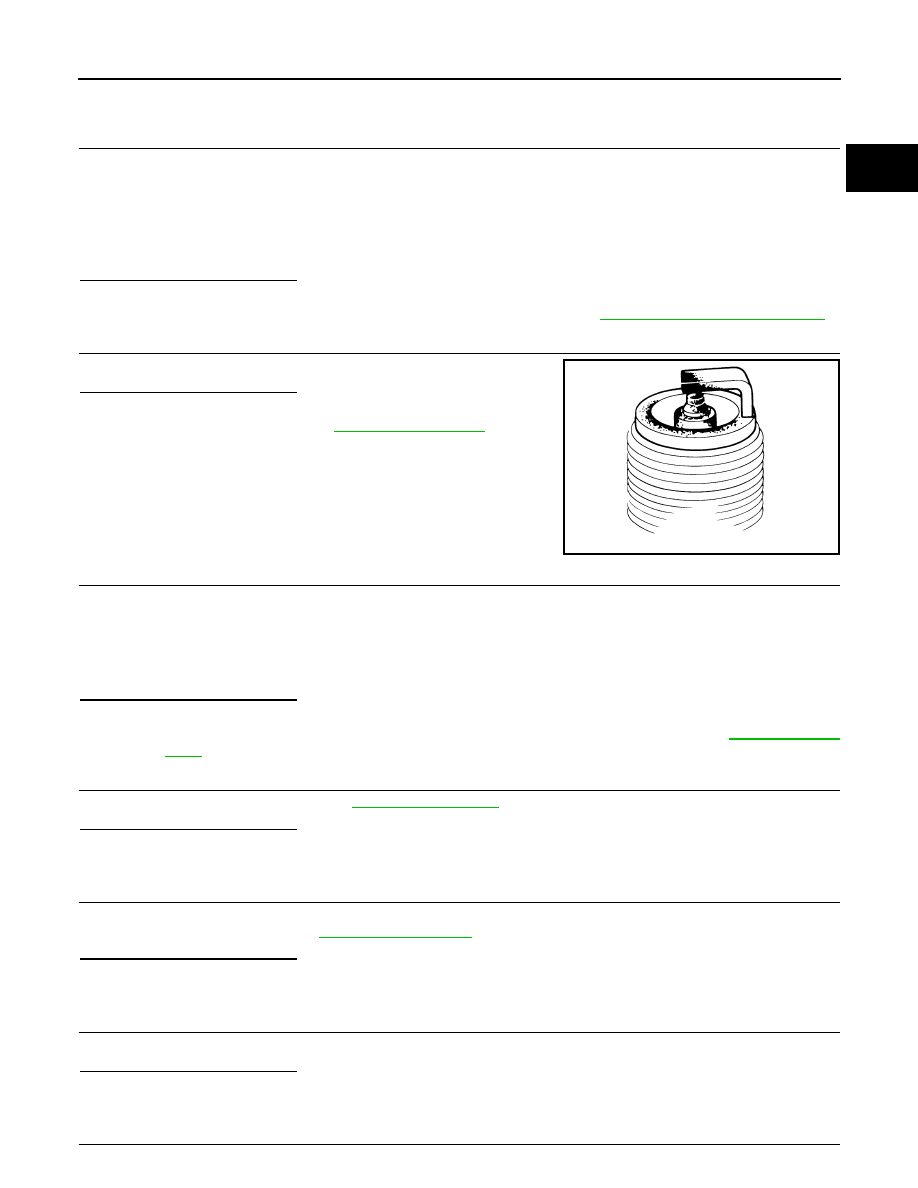
10. Fix ignition coil using a rope etc. with gap of 13 - 17 mm (0.52 -
0.66 in) between the edge of the spark plug and grounded metal
portion as shown in the figure.
11. Crank engine for approximately 3 seconds, and check whether
spark is generated between the spark plug and the grounded
metal portion.
CAUTION:
• Never place the spark plug and the ignition coil within 50
cm (19.7 in) each other. Be careful not to get an electrical
shock while checking, because the electrical discharge
voltage becomes 20 kV or more.
• It might damage the ignition coil if the gap of more than 17 mm (0.66 in) is made.
NOTE:
When the gap is less than 13 mm (0.52 in), a spark might be generated even if the coil is malfunc-
tioning.
Is the inspection result normal?
Clicking sound should be heard.
PBIB3332E
Spark should be generated.
JMBIA1552ZZ
JMBIA0066GB
P0300, P0301, P0302, P0303, P0304, P0305, P0306, P0307, P0308 MISFIRE
EC-867
< DTC/CIRCUIT DIAGNOSIS >
[VK50VE]
C
D
E
F
G
H
I
J
K
L
M
A
EC
N
P
O
YES
>> GO TO 9.
NO
>> GO TO 6.
6.
CHECK FUNCTION OF IGNITION COIL-II
1.
Turn ignition switch OFF.
2.
Disconnect spark plug and connect a non-malfunctioning spark plug.
3.
Crank engine for approximately 3 seconds, and recheck whether spark is generated between the spark
plug and the grounded metal portion.
Is the inspection result normal?
YES
>> GO TO 7.
NO
>> Check ignition coil, power transistor and their circuits. Refer to
EC-1114, "Diagnosis Procedure"
7.
CHECK SPARK PLUG
Check the initial spark plug for fouling, etc.
Is the inspection result normal?
YES
>> Replace spark plug(s) with standard type one(s). For
spark plug type, refer to
NO
>> Repair or clean spark plug. Then GO TO 8.
8.
CHECK FUNCTION OF IGNITION COIL-III
1.
Reconnect the initial spark plugs.
2.
Crank engine for approximately 3 seconds, and recheck whether spark is generated between the spark
plug and the grounded portion.
Is the inspection result normal?
YES
>> INSPECTION END
NO
>> Replace spark plug(s) with standard type one(s). For spark plug type, refer to
.
9.
CHECK COMPRESSION PRESSURE
Check compression pressure. Refer to
Is the inspection result normal?
YES
>> GO TO 10.
NO
>> Check pistons, piston rings, valves, valve seats and cylinder head gaskets.
10.
CHECK FUEL PRESSURE
1.
Install all removed parts.
2.
Check fuel pressure. Refer to
Is the inspection result normal?
YES
>> GO TO 12.
NO
>> GO TO 11.
11.
DETECT MALFUNCTIONING PART
Check fuel hoses and fuel tubes for clogging.
Is the inspection result normal?
YES
>> Replace “fuel filter and fuel pump assembly”.
NO
>> Repair or replace malfunctioning part.
12.
CHECK IDLE SPEED AND IGNITION TIMING
Spark should be generated.
SEF156I
Spark should be generated.

EC-868
< DTC/CIRCUIT DIAGNOSIS >
[VK50VE]
P0300, P0301, P0302, P0303, P0304, P0305, P0306, P0307, P0308 MISFIRE
Check idle speed and ignition timing.
For procedure, refer to
EC-576, "BASIC INSPECTION : Special Repair Requirement"
For specification, refer to
Is the inspection result normal?
YES
>> GO TO 13.
NO
>> Follow the
EC-576, "BASIC INSPECTION : Special Repair Requirement"
.
13.
CHECK A/F SENSOR 1 INPUT SIGNAL CIRCUIT
1.
Turn ignition switch OFF.
2.
Disconnect corresponding A/F sensor 1 harness connector.
3.
Disconnect ECM harness connector.
4.
Check the continuity between A/F sensor 1 harness connector and ECM harness connector.
5.
Check the continuity between A/F sensor 1 harness connector and ground, or ECM harness connector
and ground.
6.
Also check harness for short to power.
Is the inspection result normal?
YES
>> GO TO 14.
NO
>> Repair open circuit, short to ground or short to power in harness or connectors.
14.
CHECK A/F SENSOR 1 HEATER
EC-762, "Component Inspection"
Is the inspection result normal?
YES
>> GO TO 15.
NO
>> Replace malfunctioning A/F sensor 1.
15.
CHECK MASS AIR FLOW SENSOR
With CONSULT-III
Check mass air flow sensor signal in “DATA MONITOR” mode with CONSULT-III.
For specification, refer to
EC-1241, "Mass Air Flow Sensor"
With GST
Check mass air flow sensor signal in Service $01 with GST.
For specification, refer to
EC-1241, "Mass Air Flow Sensor"
Is the measurement value within the specification?
YES
>> GO TO 16.
NO
>> Check connectors for rusted terminals or loose connections in the mass air flow sensor circuit or
ground. Refer to
16.
CHECK SYMPTOM MATRIX CHART
Check items on the rough idle symptom in
A/F sensor 1
ECM
Continuity
Bank
Connector
Terminal
Connector
Terminal
1
F67
1
F111
81
Existed
2
82
2
F68
1
85
2
86
A/F sensor 1
ECM
Ground
Continuity
Bank
Connector
Terminal
Connector
Terminal
1
F67
1
F111
81
Ground
Not existed
2
82
2
F68
1
85
2
86
Нет комментариевНе стесняйтесь поделиться с нами вашим ценным мнением.
Текст