Infiniti FX35, FX50 (S51). Manual — part 1066
EXT-14
< REMOVAL AND INSTALLATION >
FRONT BUMPER
6.
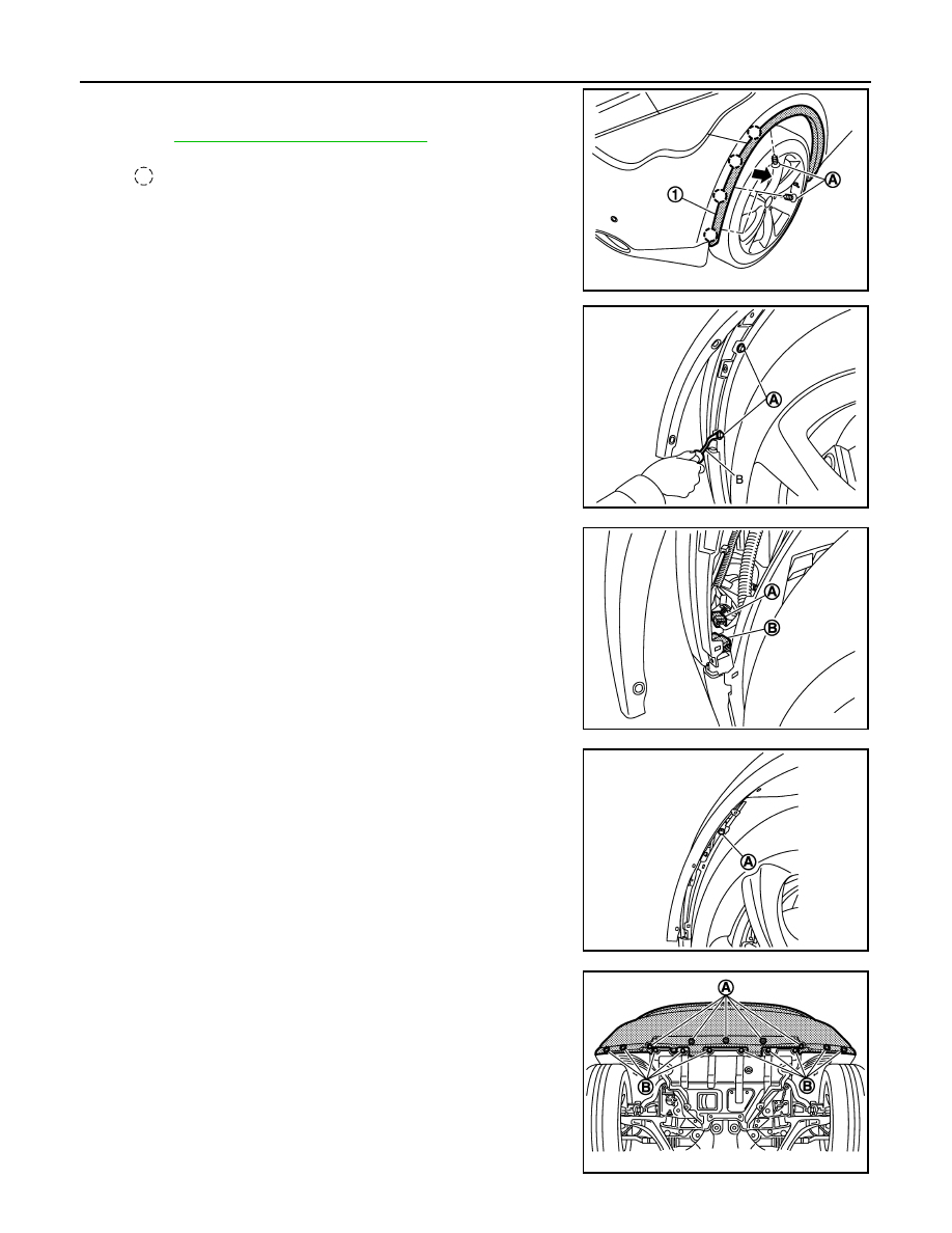
Remove front fillet molding (1) fixing screws (A) (LH/RH).
7.
Remove front fillet molding fixing clips (LH/RH).
Refer to
EXT-32, "Removal and Installation"
.
8.
Remove front fender grommets (A) with a remover tool (B).
9.
Disconnect harness connectors (A) and (B) from back side of
bumper fascia assembly (LH).
10. Remove bumper fascia assembly fixing screws (A) (LH/RH).
11. Remove bumper fascia assembly lower fixing clips (A) and bolts
(B).
: Clip
JMKIA2698ZZ
JMKIA2699ZZ
JMKIA2702ZZ
JMKIA2701ZZ
JMKIA2700ZZ
FRONT BUMPER
EXT-15
< REMOVAL AND INSTALLATION >
C
D
E
F
G
H
I
J
L
M
A
B
EXT
N
O
P
12. Pull both side of the bumper fascia assembly toward the vehicle side to disengage both side of the
bumper fascia assembly from bumper side brackets (LH/RH).
13. Remove bumper fascia assembly.
CAUTION:
When removing bumper fascia, 2 workers are required so as to prevent it from dropping.
14. Remove the following parts after removing bumper fascia.
• Hood top seal assembly.
• Front grille. Refer to
EXT-20, "Removal and Installation"
• Front bumper side stiffeners (LH/RH).
• Sonar sensors (LH/RH). Refer to
AV-359, "FRONT : Removal and Installation"
• License plate bracket.
• Front fog lamp finishers (LH/RH).
• Front fog lamps (LH/RH). Refer to
EXL-231, "Removal and Installation"
.
• Bumper fascia assembly lower.
• Front camera. Refer to
AV-352, "Removal and Installation"
15. Remove bumper energy absorber.
16. Remove bumper reinforcement mounting nuts and bolts, and then remove bumper reinforcement with
power tool.
INSTALLATION
Install in the reverse order of removal.
CAUTION:
Perform camera image calibration. Refer to
AV-245, "CALIBRATING CAMERA IMAGE (AROUND VIEW
.
NOTE:
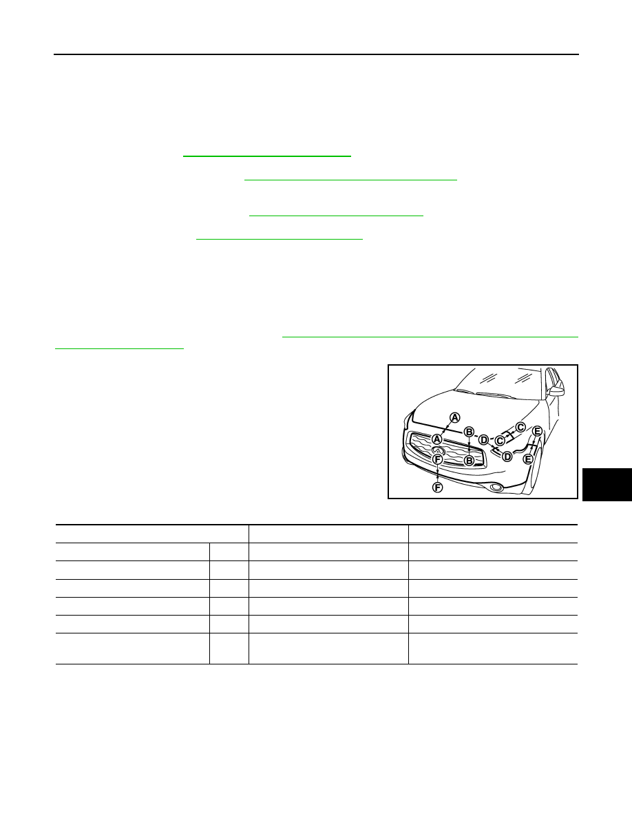
After installing, perform fitting adjustment.
JMKIA2705ZZ
Portion
Clearance
Surface height difference
Front bumper – Hood
A – A
2.5 – 5.5 mm (0.098 – 0.217 in)
−
2.0 – 0.5 mm (
−
0.079 – 0.020 in)
Front bumper – Front grille
B – B
0.0 – 2.0 mm (0.000 – 0.079 in)
—
Front bumper – Front fender
C – C
0.0 – 0.5 mm (0.000 – 0.020 in)
−
0.5 – 0.5 mm (
−
0.020 – 0.020 in)
Front bumper – Headlamp
D – D
0.2 – 3.0 mm (0.008 – 0.118 in)
—
Front bumper – Front fender
E – E
0.0 – 0.8 mm (0.000 – 0.031 in)
−
1.0 – 1.0 mm (
−
0.039 – 0.039 in)
Front bumper upper – Front
bumper lower
F – F
0.0 – 0.7 mm (0.000 – 0.028 in)
—
EXT-16
< REMOVAL AND INSTALLATION >
REAR BUMPER
REAR BUMPER
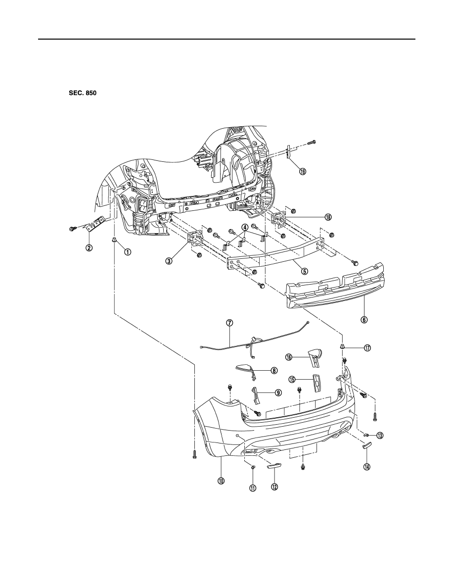
Exploded View
INFOID:0000000005248859
1.
Bumper side grommet LH
2.
Bumper side bracket LH
3.
Bumper stay LH
4.
Bumper lower retainer
5.
Bumper reinforcement
6.
Energy absorber
JMKIA2706ZZ
REAR BUMPER
EXT-17
< REMOVAL AND INSTALLATION >
C
D
E
F
G
H
I
J
L
M
A
B
EXT
N
O
P
Removal and Installation
INFOID:0000000005248860
REMOVAL
CAUTION:
Bumper fascia is made of resin. Never apply strong force to it, and be careful to prevent contact with
oil.
1.
Fully open back door.
2.
Remove rear combination lamps (LH/RH). Refer to
EXL-240, "Removal and Installation"
.
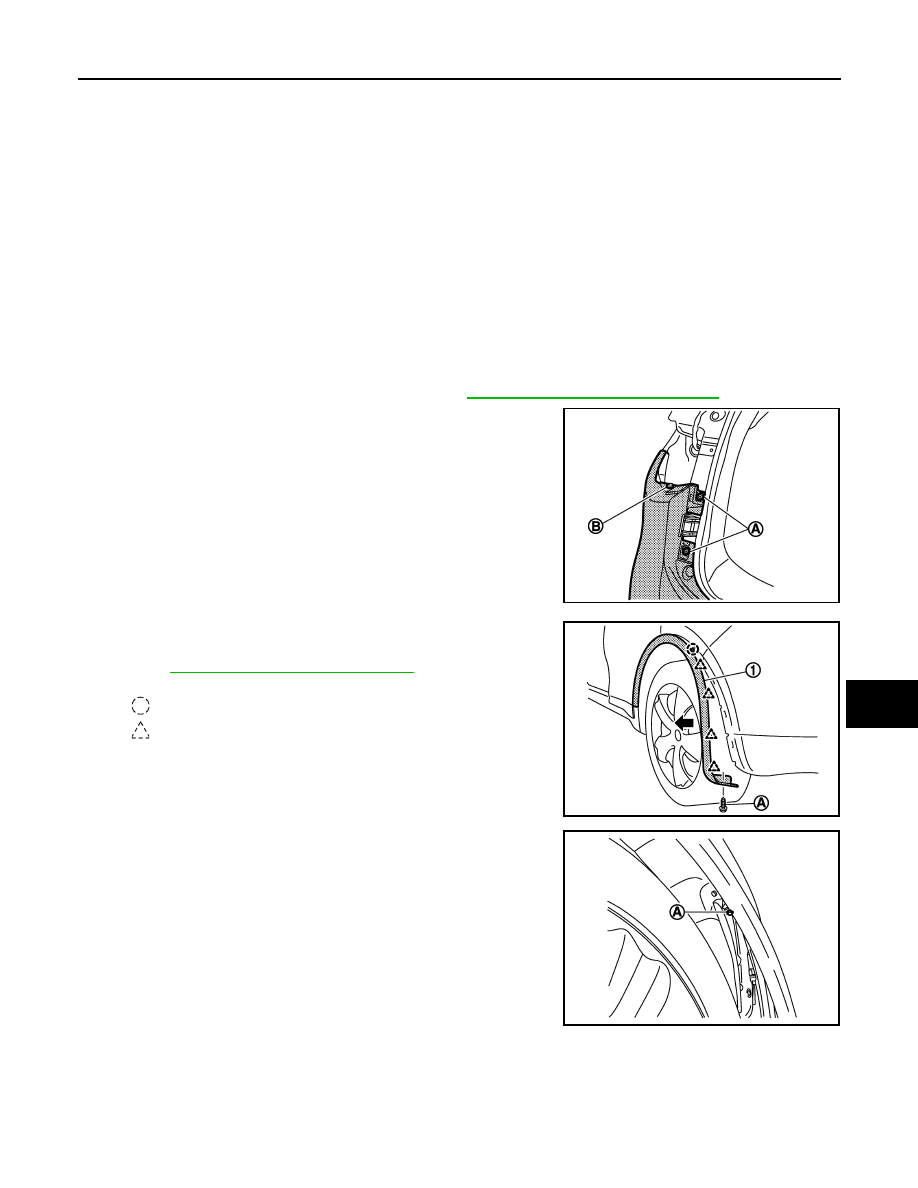
3.
Remove bolts (A) and clips (B) (LH/RH) located under rear com-
bination lamps (LH/RH).
4.
Remove rear fillet moldings (1) fixing screws (A) (LH/RH).
5.
Remove rear fillet moldings fixing pawls and clips (LH/RH).
Refer to
EXT-32, "Removal and Installation"
.
6.
Remove bumper fascia assembly fixing screws (A) (LH/RH).
7.
Bumper sub harness
8.
Rear combination lamp upper finisher
LH
9.
Rear combination lamp lower finisher
LH
10. Bumper fascia assembly
11.
Sonar sensor LH
12. Reflex reflector LH
13. Sonar sensor RH
14. Reflex reflector RH
15. Rear combination lamp lower finisher
RH
16. Rear combination lamp upper finisher
RH
17. Bumper side grommet RH
18. Bumper stay RH
19. Bumper side bracket RH
JMKIA2708ZZ
: Clip
: Pawl
JMKIA2709ZZ
JMKIA2710ZZ
Нет комментариевНе стесняйтесь поделиться с нами вашим ценным мнением.
Текст