Infiniti FX35, FX50 (S51). Manual — part 1166
DIAGNOSIS SYSTEM (UNIFIED METER & A/C AMP.)
HAC-61
< SYSTEM DESCRIPTION >
[AUTOMATIC AIR CONDITIONER]
C
D
E
F
G
H
J
K
L
M
A
B
HAC
N
O
P
1.
Press intake switch.
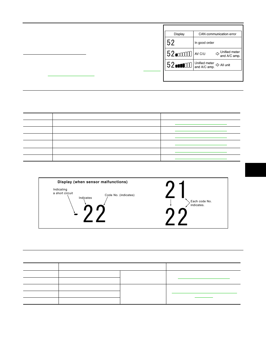
2.
CAN communication error between each unit that uses the uni-
fied meter and A/C amp. can be detected as self-diagnosis
results. (The display of each error will blink twice for 0.5 second
intervals if plural errors occur.)
Is the inspection result normal?
YES
>> INSPECTION END
NO
>> Go to CAN communication (Unified meter and A/C amp.
– AV control unit). Refer to
11.
CHECK MALFUNCTIONING SENSOR AND DOOR MOTOR
Refer to the following chart for malfunctioning code No.
(Corresponding code Nos. indicates 1 second each if two or more sensors and door motors malfunction.)
(Corresponding code Nos. indicates 0.5 second each if two door motors malfunction.)
*: Perform self-diagnosis STEP-2 under sunshine.
When performing indoors, aim a light (more than 60 W) at sunload sensor, otherwise code No. 25 indicates
despite that sunload sensor is functioning normally.
>> INSPECTION END
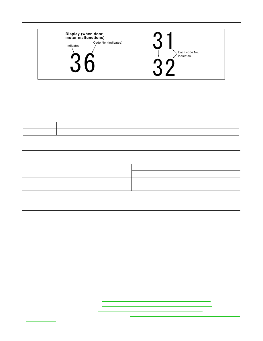
12.
CHECK MALFUNCTIONING DOOR MOTOR POSITION SWITCH
Mode and/or intake door motor PBR(s) is/are malfunctioning.
(Corresponding code Nos. indicates 1 second each if two or more mode or intake door motors malfunction.)
*1: The following display pattern will appear if mode door motor harness connector is disconnected.
31
→
32
→
Return to 31
*2: The following display pattern will appear if intake door motor harness connector is disconnected.
JSIIA0138GB
Code No.
Malfunctioning sensor and door motor (Including circuits)
Reference
21 /
−
21
Ambient sensor
22 /
−
22
In-vehicle sensor
24 /
−
24
Intake sensor
25 /
−
25
Sunload sensor
*
26 /
−
26
Air mix door motor PBR (Driver side)
27 /
−
27
Air mix door motor PBR (Passenger side)
SJIA1781E
Code No.
*1 *2
Mode or intake door position
Reference
31
VENT
Mode door motor
32
DEF
37
FRE
Intake door motor
HAC-76, "WITHOUT ACCS : Diagnosis
38
20% FRE
39
REC
HAC-62
< SYSTEM DESCRIPTION >
[AUTOMATIC AIR CONDITIONER]
DIAGNOSIS SYSTEM (UNIFIED METER & A/C AMP.)
37
→
38
→
39
→
Return to 37
>> INSPECTION END
WITHOUT ACCS : CONSULT-III Function
INFOID:0000000005246244
CONSULT-III APPLICATION ITEMS
CONSULT-III can display each diagnosis item using the diagnosis test modes shown as per the following.
DATA MONITOR
Display Item List
WITH ACCS
WITH ACCS : Diagnosis Description
INFOID:0000000005246245
SELF-DIAGNOSIS SYSTEM
The self-diagnosis system is built into the unified meter and A/C amp. to quickly locate the cause of malfunc-
tions.
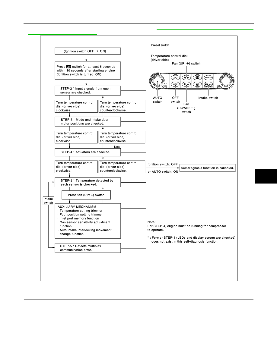
SELF-DIAGNOSIS FUNCTION
• The self-diagnosis system diagnoses sensors, door motors, blower motor, etc. by system line. Refer to appli-
cable sections (items) for details. Shifting from normal control to the self-diagnosis system is accomplished
by starting the engine (turning the ignition switch ON) and pressing OFF switch for at least 5 seconds. The
OFF switch must be pressed within 10 seconds after starting the engine (ignition switch is turned ON). This
system is canceled by either pressing AUTO switch or turning the ignition switch OFF. Shifting from one step
is accomplished by means of turning temperature control dial (driver side), as required.
• Shifting from STEP-5 to AUXILIARY MECHANISM is accomplished by means of pressing fan (UP: +)
switch.
- Temperature setting trimmer. Refer to
HAC-11, "WITH ACCS : Temperature Setting Trimmer"
- Foot position setting trimmer. Refer to
HAC-12, "WITH ACCS : Foot Position Setting Trimmer"
.
- Inlet port memory function. Refer to
HAC-13, "WITH ACCS : Inlet Port Memory Function"
- Gas sensor sensitivity adjustment function. Refer to
HAC-13, "WITH ACCS : Gas Sensor Sensitivity Adjust-
.
SJIA1782E
System part
Check item, diagnosis mode
Description
ECM
Data monitor
Displays ECM input data in real time.
Monitor Item
Condition
Value/Status
IGNITION SW
Ignition switch OFF
→
ON
Off
→
On
HEATER FAN SW
Ignition switch ON
Blower fan motor switch ON
On
Blower fan motor switch OFF
Off
AIR COND SIG
Ignition switch ON
Compressor ON
On
Compressor OFF
Off
REFRIGERANT PRESSURE
SENSOR
• Engine is running
• Warm-up condition
• Both A/C switch and blower fan motor switch: ON (Compressor
operates)
1.0 – 4.0 V
DIAGNOSIS SYSTEM (UNIFIED METER & A/C AMP.)
HAC-63
< SYSTEM DESCRIPTION >
[AUTOMATIC AIR CONDITIONER]
C
D
E
F
G
H
J
K
L
M
A
B
HAC
N
O
P
- Auto intake interlocking movement change function. Refer to
HAC-14, "WITH ACCS : Auto Intake Interlock-
.
CONFORMATION METHOD
1.
SET IN SELF-DIAGNOSIS MODE
1.
Turn ignition switch ON.
2.
Set in self-diagnosis mode as per the following. Press OFF switch for at least 5 seconds Within 10 sec-
onds after starting engine (ignition switch is turned ON).
NOTE:
• If battery voltage drops below 12 V during diagnosis STEP-3, door motor speed becomes slower and as a
result, the system may generate an error even when operation is normal. Start engine before performing this
diagnosis to avoid this.
• Former STEP-1 (indicators and display screen are checked) does not exist in this self-diagnosis function.
JMIIA0490GB
HAC-64
< SYSTEM DESCRIPTION >
[AUTOMATIC AIR CONDITIONER]
DIAGNOSIS SYSTEM (UNIFIED METER & A/C AMP.)
• OFF switch may not be recognized according to the timing of pressing it. Operate OFF switch after the
intake switch indicators are turned ON.
>> GO TO 2.
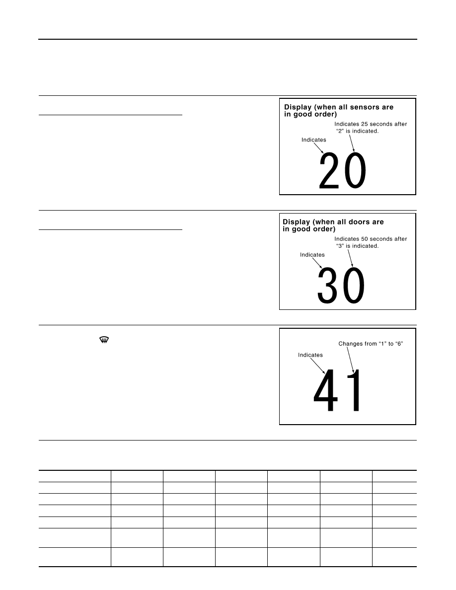
2.
STEP-2: SENSOR AND DOOR MOTOR CIRCUITS ARE CHECKED FOR OPEN OR SHORT CIRCUIT
Does code No. 20 appear on the display?
YES
>> GO TO 3.
NO
>> GO TO 11.
3.
STEP-3: MODE DOOR AND INTAKE DOOR POSITIONS ARE CHECKED
Turn temperature control dial (driver side) clockwise.
Does code No. 30 appear on the display?
YES
>> GO TO 4.
NO
>> GO TO 12.
4.
STEP-4: OPERATION OF EACH DOOR MOTOR IS CHECKED
1.
Turn temperature control dial (driver side) clockwise.
2.
Press DEF (
) switch. Code No. of each door motor test is
indicated on the display.
>> GO TO 5.
5.
CHECK ACTUATORS
Refer to the following chart and check discharge air flow, air temperature, blower motor duty ratio and com-
pressor operation.
SJIA1778E
SJIA1779E
SJIA1780E
Code No.
41
42
43
44
45
46
Mode door position
VENT
B/L 1
B/L 2
FOOT
D/F
DEF
Intake door position
REC
REC
20% FRE
FRE
FRE
FRE
Air mix door position
FULL COOL
FULL COOL
FULL HOT
FULL HOT
FULL HOT
FULL HOT
Blower motor duty ratio
37%
91%
65%
65%
65%
91%
Compressor (Magnet
clutch)
ON
ON
OFF
OFF
ON
ON
Electronic control valve
(ECV) duty ratio
100%
100%
0%
0%
50%
100%
Нет комментариевНе стесняйтесь поделиться с нами вашим ценным мнением.
Текст