Infiniti FX35, FX50 (S51). Manual — part 1167
DIAGNOSIS SYSTEM (UNIFIED METER & A/C AMP.)
HAC-65
< SYSTEM DESCRIPTION >
[AUTOMATIC AIR CONDITIONER]
C
D
E
F
G
H
J
K
L
M
A
B
HAC
N
O
P
Checks must be made visually, by listening the sound, or by touching air outlets with hand, etc. for improper
operation. Refer to
.
Is this inspection result normal?
YES
>> GO TO 6.
NO-1
>> Air outlet does not change. Refer to
.
NO-2
>> Intake door does not change. Refer to
HAC-78, "WITH ACCS : Diagnosis Procedure"
NO-3
>> Discharge air temperature (driver side) does not change. Refer to
.
NO-4
>> Discharge air temperature (passenger side) does not change. Refer to
NO-5
>> Blower motor operation is malfunctioning. Refer to
.
NO-6
>> Magnet clutch does not engage. Refer to
NO-7
>> Plasmacluster system does not operate. Refer to
HAC-102, "Diagnosis Procedure"
.
6.
STEP-5: TEMPERATURE OF EACH SENSOR IS CHECKED
1.
Turn temperature control dial (driver side) clockwise.
2.
Code No. 51 appears on the display.
>> GO TO 7.
7.
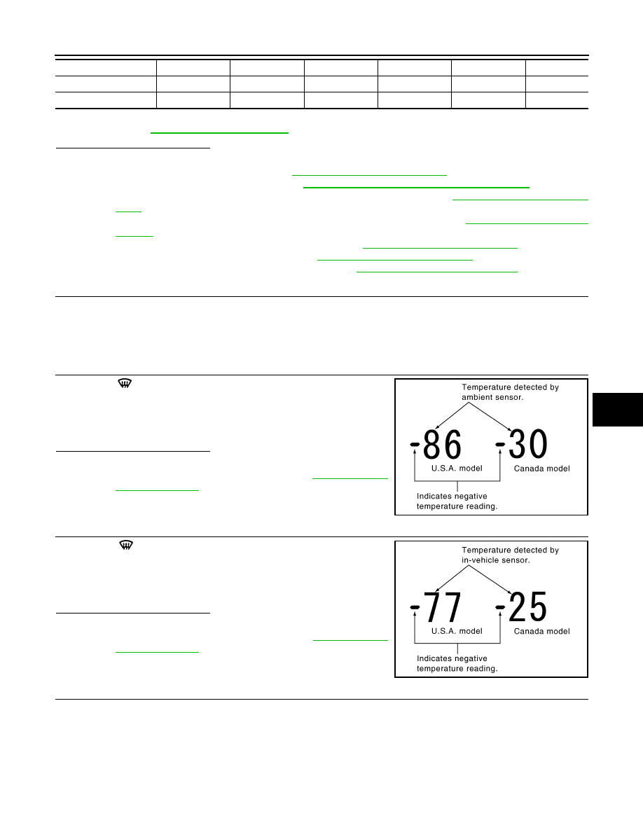
CHECK AMBIENT SENSOR
Press DEF (
) switch one time. Temperature detected by ambient
sensor is indicated on the display.
NOTE:
Check sensor circuit first if the temperature indicated on the display
greatly differs from the actual temperature, and then check sensor.
Is this inspection result normal?
YES
>> GO TO 8.
NO
>> Go to Ambient Sensor Circuit. Refer to
.
8.
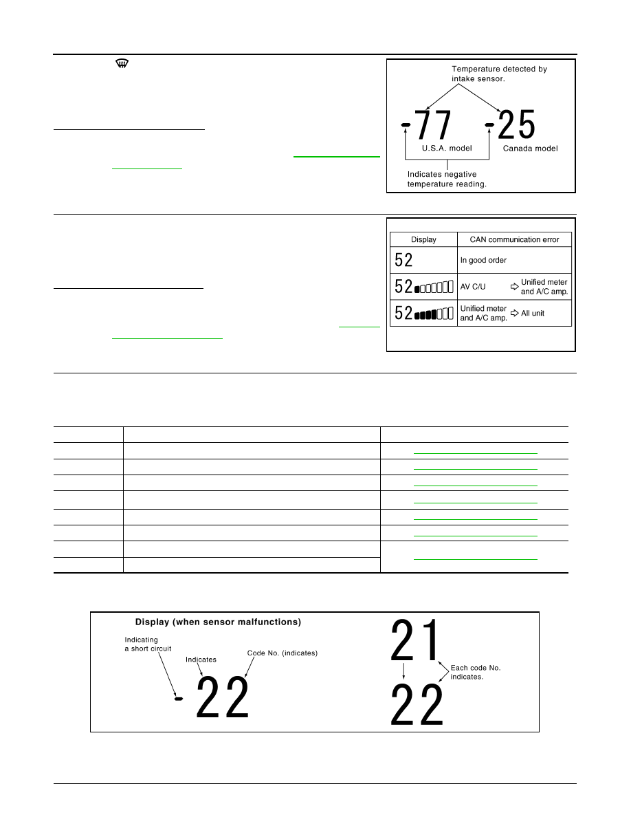
CHECK IN-VEHICLE SENSOR
Press DEF (
) switch for the second time. Temperature detected
by in-vehicle sensor is indicated on the display.
NOTE:
Check sensor circuit first if the temperature indicated on the display
greatly differs from the actual temperature, and then check sensor.
Is this inspection result normal?
YES
>> GO TO 9.
NO
>> Go to In-vehicle Sensor Circuit. Refer to
.
9.
CHECK INTAKE SENSOR
Ionizer
ON
ON
ON
ON
ON
OFF
Ion mode
CLEAN
QUICK CLEAN
QUICK CLEAN
QUICK CLEAN
QUICK CLEAN
OFF
Code No.
41
42
43
44
45
46
PJIA0151E
PJIA0152E
HAC-66
< SYSTEM DESCRIPTION >
[AUTOMATIC AIR CONDITIONER]
DIAGNOSIS SYSTEM (UNIFIED METER & A/C AMP.)
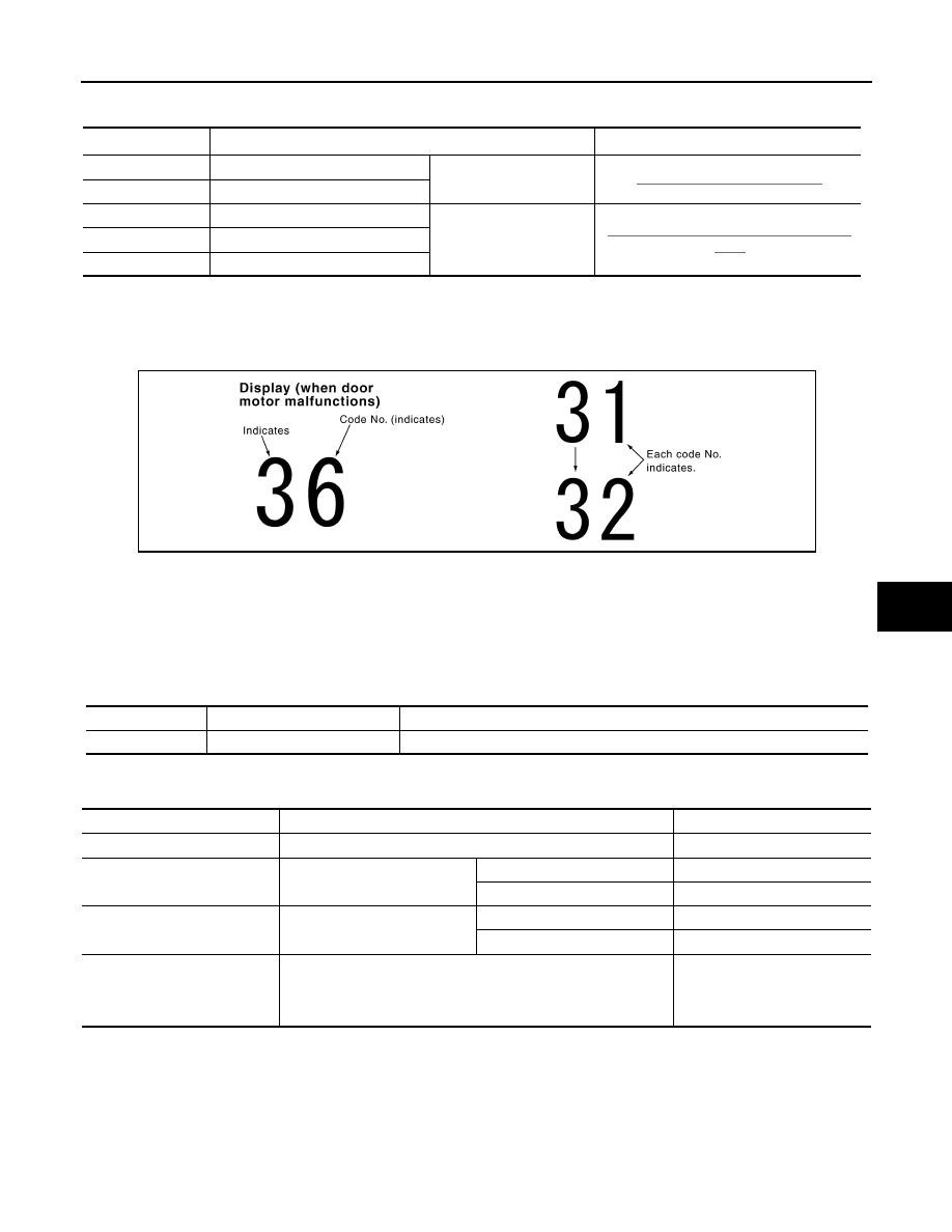
Press DEF (
) switch for the third time. Temperature detected by
intake sensor is indicated on the display.
NOTE:
Check sensor circuit first if the temperature indicated on the display
greatly differs from the actual temperature, and then check sensor.
Is this inspection result normal?
YES
>> GO TO 10.
NO
>> Go to Intake Sensor Circuit. Refer to
10.
CHECK CAN COMMUNICATION ERROR
1.
Press intake switch.
2.
CAN communication error between each unit that uses the uni-
fied meter and A/C amp. can be detected as self-diagnosis
results. (The display of each error will blink twice for 0.5 second
intervals if plural errors occur.)
Is the inspection result normal?
YES
>> INSPECTION END
NO
>> Go to CAN communication (Unified meter and A/C amp.
11.
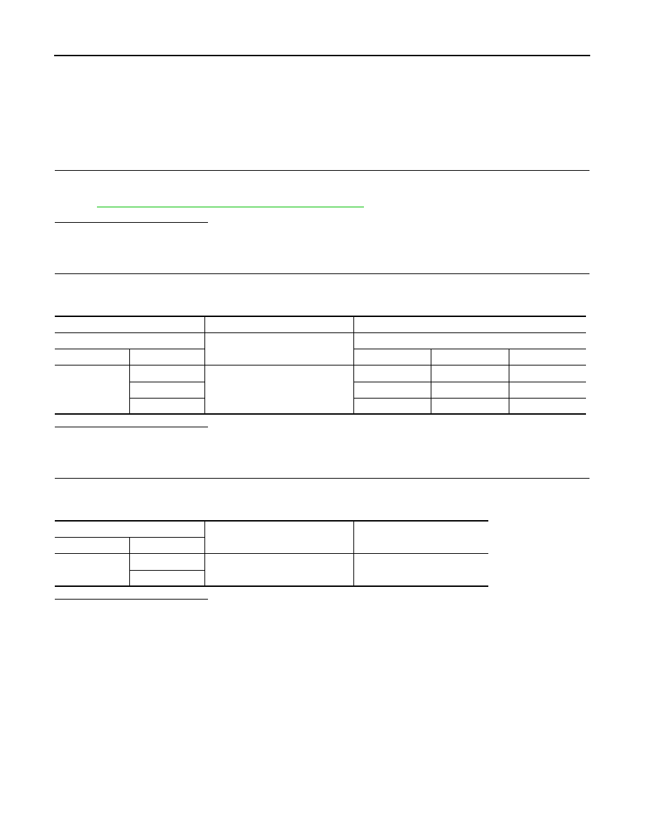
CHECK MALFUNCTIONING SENSOR AND DOOR MOTOR
Refer to the following chart for malfunctioning code No.
(Corresponding code Nos. indicates 1 second each if two or more sensors and door motors malfunction.)
(Corresponding code Nos. indicates 0.5 second each if two door motors malfunction.)
*: Perform self-diagnosis STEP-2 under sunshine.
When performing indoors, aim a light (more than 60 W) at sunload sensor, otherwise code No. 25 indicates
despite that sunload sensor is functioning normally.
>> INSPECTION END
12.
CHECK MALFUNCTIONING DOOR MOTOR POSITION SWITCH
PJIA0153E
JSIIA0138GB
Code No.
Malfunctioning sensor and door motor (Including circuits)
Reference
21 /
−
21
Ambient sensor
22 /
−
22
In-vehicle sensor
24 /
−
24
Intake sensor
25 /
−
25
Sunload sensor
*
26 /
−
26
Air mix door motor PBR (Driver side)
27 /
−
27
Air mix door motor PBR (Passenger side)
28 /
−
28
Gas sensor
29 /
−
29
Harness of gas sensor
SJIA1781E
DIAGNOSIS SYSTEM (UNIFIED METER & A/C AMP.)
HAC-67
< SYSTEM DESCRIPTION >
[AUTOMATIC AIR CONDITIONER]
C
D
E
F
G
H
J
K
L
M
A
B
HAC
N
O
P
Mode and/or intake door motor PBR(s) is/are malfunctioning.
(Corresponding code Nos. indicates 1 second each if two or more mode or intake door motors malfunction.)
*1: The following display pattern will appear if mode door motor harness connector is disconnected.
31
→
32
→
Return to 31
*2: The following display pattern will appear if intake door motor harness connector is disconnected.
37
→
38
→
39
→
Return to 37
>> INSPECTION END
WITH ACCS : CONSULT-III Function
INFOID:0000000005246246
CONSULT-III APPLICATION ITEMS
CONSULT-III can display each diagnosis item using the diagnosis test modes shown as per the following.
DATA MONITOR
Display Item List
Code No.
*1 *2
Mode or intake door position
Reference
31
VENT
Mode door motor
32
DEF
37
FRE
Intake door motor
HAC-78, "WITH ACCS : Diagnosis Proce-
38
20% FRE
39
REC
SJIA1782E
System part
Check item, diagnosis mode
Description
ECM
Data monitor
Displays ECM input data in real time.
Monitor Item
Condition
Value/Status
IGNITION SW
Ignition switch OFF
→
ON
Off
→
On
HEATER FAN SW
Ignition switch ON
Blower fan motor switch ON
On
Blower fan motor switch OFF
Off
AIR COND SIG
Ignition switch ON
Compressor ON
On
Compressor OFF
Off
REFRIGERANT PRESSURE
SENSOR
• Engine is running
• Warm-up condition
• Both A/C switch and blower fan motor switch: ON (Compressor
operates)
1.0 – 4.0 V
HAC-68
< DTC/CIRCUIT DIAGNOSIS >
[AUTOMATIC AIR CONDITIONER]
POWER SUPPLY AND GROUND CIRCUIT
DTC/CIRCUIT DIAGNOSIS
POWER SUPPLY AND GROUND CIRCUIT
UNIFIED METER AND A/C AMP.
UNIFIED METER AND A/C AMP. : Diagnosis Procedure
INFOID:0000000005246247
1.
CHECK FUSE
Check 10A fuses [Nos. 3, 6 and 19, located in the fuse block (J/B)].
NOTE:
Refer to
PG-156, "Fuse, Connector and Terminal Arrangement"
Is the inspection result normal?
YES
>> GO TO 2.
NO
>> Check harness for short circuit and replace fuse.
2.
CHECK POWER SUPPLY CIRCUIT FOR UNIFIED METER AND A/C AMP.
1.
Disconnect unified meter and A/C amp. connector.
2.
Check voltage between unified meter and A/C amp. harness connector and ground.
Is the inspection result normal?
YES
>> GO TO 3.
NO
>> Repair harness or connector.
3.
CHECK GROUND CIRCUIT FOR UNIFIED METER AND A/C AMP.
1.
Turn ignition switch OFF.
2.
Check continuity between unified meter and A/C amp. harness connector and ground.
Is the inspection result normal?
YES
>> INSPECTION END
NO
>> Repair harness or connector.
(+)
(
−
)
Voltage
Unified meter and A/C amp.
—
Ignition switch position
Connector
Terminal
OFF
ACC
ON
M67
41
Ground
Approx. 0 V
Battery voltage
Battery voltage
53
Approx. 0 V
Approx. 0 V
Battery voltage
54
Battery voltage
Battery voltage
Battery voltage
Unified meter and A/C amp.
—
Continuity
Connector
Terminal
M67
55
Ground
Existed
71
Нет комментариевНе стесняйтесь поделиться с нами вашим ценным мнением.
Текст