Infiniti FX35, FX50 (S51). Manual — part 541
REMOTE KEYLESS ENTRY RECEIVER
DLK-287
< REMOVAL AND INSTALLATION >
C
D
E
F
G
H
I
J
L
M
A
B
DLK
N
O
P
REMOTE KEYLESS ENTRY RECEIVER
Exploded View
INFOID:0000000005239797
.
Removal and Installation
INFOID:0000000005239798
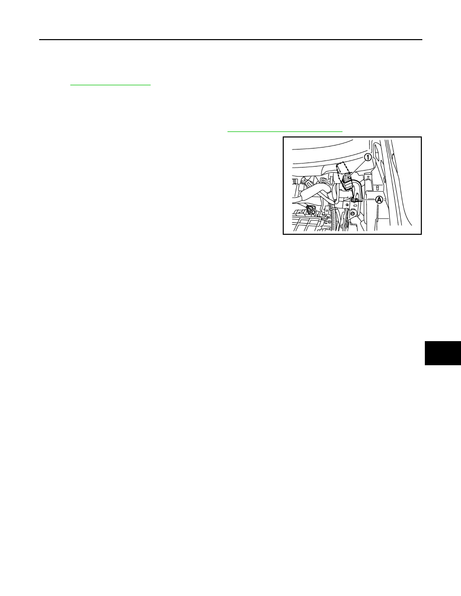
REMOVAL
1.
Remove the instrument lower panel RH. Refer to
IP-12, "Removal and Installation"
2.
Remove the remote keyless entry receiver mounting screw (A),
and then remove remote keyless entry receiver (1).
INSTALLATION
Install in the reverse order of removal.
JMKIA2252ZZ
DLK-288
< REMOVAL AND INSTALLATION >
INTELLIGENT KEY BATTERY
INTELLIGENT KEY BATTERY
Removal and Installation
INFOID:0000000005239799
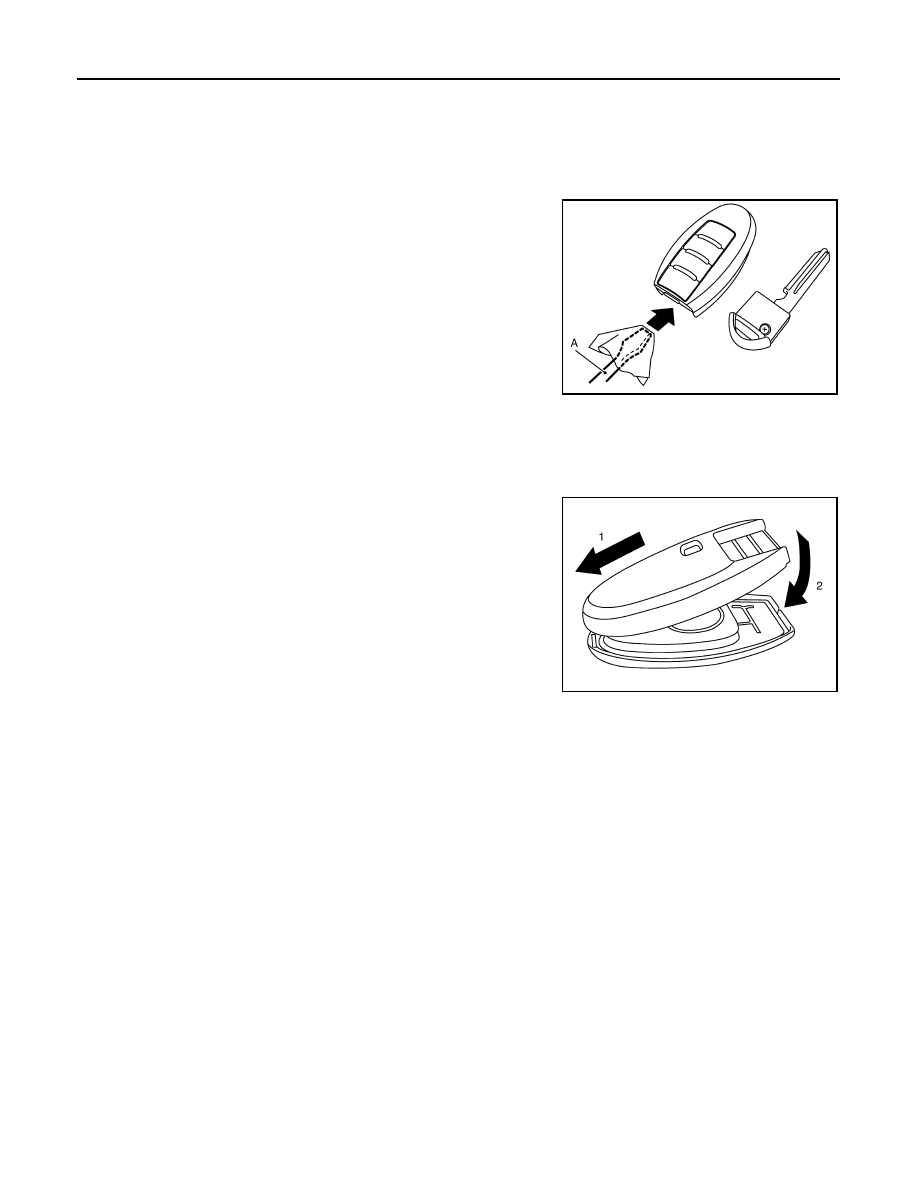
1.
Release the lock knob at the back of the Intelligent Key and remove the mechanical key.
2.
Insert a flat-bladed screwdriver (A) wrapped in a cloth into the
slit of the corner and twist it to separate the upper part from the
lower part.
CAUTION:
• Never touch the circuit board or battery terminal.
• The key fob is water-resistant. However, if it does get wet,
immediately wipe it dry.
3.
Replace the battery with new one.
4.
Align the tips of the upper and lower parts, and then push them
together until it is securely closed.
CAUTION:
• When replacing battery, keep dirt, grease, and other for-
eign matter off the electrode contact area.
• After replacing the battery, check that all Intelligent Key
functions work normally.
PIIB6221E
Battery replacement
: Coin-type lithium battery (CR2025)
PIIB6222E
DLN-1
TRANSMISSION & DRIVELINE
C
E
F
G
H
I
J
K
L
M
SECTION
DLN
A
B
DLN
N
O
P
CONTENTS
DRIVELINE
TRANSFER: ETX13C
BASIC INSPECTION . . . . . . . . .
DIAGNOSIS AND REPAIR WORK FLOW . . .
Work Flow . . . . . . . . . . . . . . . .....
SYSTEM DESCRIPTION . . . . . . . ..
AWD SYSTEM . . . . . . . . . . . . . .
System Diagram . . . . . . . . . . . . . ....
System Description . . . . . . . . . . . . .
Component Parts Location . . . . . . . . . ..
Component Description . . . . . . . . . . ...
DIAGNOSIS SYSTEM (AWD CONTROL
UNIT) . . . . . . . . . . . . . . . . ..
CONSULT-III Function (ALL MODE AWD/4WD) .
DTC/CIRCUIT DIAGNOSIS . . . . . . .
C1201 AWD CONTROL UNIT . . . . . . .
Description . . . . . . . . . . . . . . . ..
DTC Logic . . . . . . . . . . . . . . . ...
Diagnosis Procedure . . . . . . . . . . . ...
C1203 ABS ACTUATOR AND ELECTRIC
UNIT (CONTROL UNIT) . . . . . . . . . .
Description . . . . . . . . . . . . . . . ..
DTC Logic . . . . . . . . . . . . . . . ...
Diagnosis Procedure . . . . . . . . . . . ...
C1204 AWD SOLENOID . . . . . . . . .
Description . . . . . . . . . . . . . . . ..
DTC Logic . . . . . . . . . . . . . . . ...
Diagnosis Procedure . . . . . . . . . . . ...
Component Inspection . . . . . . . . . . .
C1205 AWD ACTUATOR RELAY . . . . . .
Description . . . . . . . . . . . . . . . ..
DTC Logic . . . . . . . . . . . . . . . ...
Diagnosis Procedure . . . . . . . . . . . ...
C1210 ECM . . . . . . . . . . . . . ...
Description . . . . . . . . . . . . . . . ...
DTC Logic . . . . . . . . . . . . . . . .
Diagnosis Procedure . . . . . . . . . . . ...
P1804 TRANSFER CONTROL UNIT . . . .
Description . . . . . . . . . . . . . . . ...
DTC Logic . . . . . . . . . . . . . . . .
Diagnosis Procedure . . . . . . . . . . . ...
P1809 TRANSFER CONTROL UNIT . . . .
Description . . . . . . . . . . . . . . . ...
DTC Logic . . . . . . . . . . . . . . . .
Diagnosis Procedure . . . . . . . . . . . ...
P1826 TRANSFER FLUID TEMPERATURE .
Description . . . . . . . . . . . . . . . ...
DTC Logic . . . . . . . . . . . . . . . .
Diagnosis Procedure . . . . . . . . . . . ...
Component Inspection . . . . . . . . . . . .
U1000 CAN COMM CIRCUIT . . . . . . ...
Description . . . . . . . . . . . . . . . ...
DTC Logic . . . . . . . . . . . . . . . .
Diagnosis Procedure . . . . . . . . . . . ...
U1010 CONTROL UNIT (CAN) . . . . . . .
Description . . . . . . . . . . . . . . . ...
DTC Logic . . . . . . . . . . . . . . . .
Diagnosis Procedure . . . . . . . . . . . ...
POWER SUPPLY AND GROUND CIRCUIT .
Description . . . . . . . . . . . . . . . ...
Diagnosis Procedure . . . . . . . . . . . ...
AWD WARNING LAMP . . . . . . . . .
Description . . . . . . . . . . . . . . . ...
Component Function Check . . . . . . . . .
Diagnosis Procedure . . . . . . . . . . . ...
DLN-2
AWD CONTROL UNIT . . . . . . . . . ...
Reference Value . . . . . . . . . . . . . .
Wiring Diagram - AWD SYSTEM - . . . . . . .
Fail-Safe . . . . . . . . . . . . . . . . .
DTC Inspection Priority Chart . . . . . . . . .
DTC Index . . . . . . . . . . . . . . . ..
SYMPTOM DIAGNOSIS . . . . . . . .
AWD WARNING LAMP DOES NOT TURN ON
...
Description . . . . . . . . . . . . . . . ..
Diagnosis Procedure . . . . . . . . . . . ..
AWD WARNING LAMP DOES NOT TURN
OFF . . . . . . . . . . . . . . . . .
Description . . . . . . . . . . . . . . . ..
Diagnosis Procedure . . . . . . . . . . . ..
HEAVY TIGHT-CORNER BRAKING SYMP-
TOM OCCURS . . . . . . . . . . . . ...
Description . . . . . . . . . . . . . . . ..
Diagnosis Procedure . . . . . . . . . . . ..
VEHICLE DOES NOT ENTER AWD MODE . .
Description . . . . . . . . . . . . . . . ..
Diagnosis Procedure . . . . . . . . . . . ..
AWD WARNING LAMP BLINKS QUICKLY . .
Description . . . . . . . . . . . . . . . ..
AWD WARNING LAMP BLINKS SLOWLY . ..
Description . . . . . . . . . . . . . . . ..
Diagnosis Procedure . . . . . . . . . . . ..
NOISE, VIBRATION AND HARSHNESS
(NVH) TROUBLESHOOTING . . . . . . .
NVH Troubleshooting Chart . . . . . . . . ...
PRECAUTION . . . . . . . . . . . .
PRECAUTIONS . . . . . . . . . . . . .
Precaution Necessary for Steering Wheel Rota-
tion after Battery Disconnect . . . . . . . . ..
Service Notice or Precautions for Transfer . . . .
PREPARATION . . . . . . . . . . ...
PREPARATION . . . . . . . . . . . . .
VQ35HR . . . . . . . . . . . . . . . . ....
VQ35HR : Special Service Tools . . . . . . ....
VQ35HR : Commercial Service Tools . . . . ....
VK50VE . . . . . . . . . . . . . . . . . .
VK50VE : Special Service Tools . . . . . . ....
VK50VE : Commercial Service Tools . . . . . .
PERIODIC MAINTENANCE . . . . . .
TRANSFER FLUID . . . . . . . . . . .
VQ35HR . . . . . . . . . . . . . . . . . .
VQ35HR : Inspection . . . . . . . . . . . ..
VQ35HR : Draining . . . . . . . . . . . . .
VQ35HR : Refilling . . . . . . . . . . . . ..
VK50VE . . . . . . . . . . . . . . . . . .
VK50VE : Inspection . . . . . . . . . . . ...
VK50VE : Draining . . . . . . . . . . . . ..
VK50VE : Refilling . . . . . . . . . . . . ...
REMOVAL AND INSTALLATION . . . ..
AWD CONTROL UNIT . . . . . . . . . ..
Exploded View . . . . . . . . . . . . . .
Removal and Installation . . . . . . . . . . .
FRONT OIL SEAL . . . . . . . . . . . .
Exploded View . . . . . . . . . . . . . .
Removal and Installation . . . . . . . . . . .
REAR OIL SEAL . . . . . . . . . . . ...
VQ35HR . . . . . . . . . . . . . . . . . .
VQ35HR : Exploded View . . . . . . . . . ...
VQ35HR : Removal and Installation . . . . . ...
VK50VE . . . . . . . . . . . . . . . . . .
VK50VE : Exploded View . . . . . . . . . .
VK50VE : Removal and Installation . . . . . .
UNIT REMOVAL AND INSTALLATION .
TRANSFER ASSEMBLY . . . . . . . . ...
VQ35HR . . . . . . . . . . . . . . . . . .
VQ35HR : Exploded View . . . . . . . . . ...
VQ35HR : Removal and Installation . . . . . ...
VK50VE . . . . . . . . . . . . . . . . . .
VK50VE : Exploded View . . . . . . . . . .
VK50VE : Removal and Installation . . . . . .
UNIT DISASSEMBLY AND ASSEMBLY ...
FRONT CASE AND REAR CASE . . . . . .
VQ35HR . . . . . . . . . . . . . . . . . .
VQ35HR : Exploded View . . . . . . . . . ...
VQ35HR : Disassembly . . . . . . . . . . ..
VQ35HR : Assembly . . . . . . . . . . . ...
VQ35HR : Inspection . . . . . . . . . . . ..
VK50VE . . . . . . . . . . . . . . . . . .
VK50VE : Exploded View . . . . . . . . . .
VK50VE : Disassembly . . . . . . . . . . ...
VK50VE : Assembly . . . . . . . . . . . .
VK50VE : Inspection . . . . . . . . . . . ...
MAIN SHAFT . . . . . . . . . . . . . .
VQ35HR . . . . . . . . . . . . . . . . . .
Нет комментариевНе стесняйтесь поделиться с нами вашим ценным мнением.
Текст