Infiniti FX35, FX50 (S51). Manual — part 1179
ECM
HAC-113
< ECU DIAGNOSIS INFORMATION >
[AUTOMATIC AIR CONDITIONER]
C
D
E
F
G
H
J
K
L
M
A
B
HAC
N
O
P
37
(LG)
128
(B)
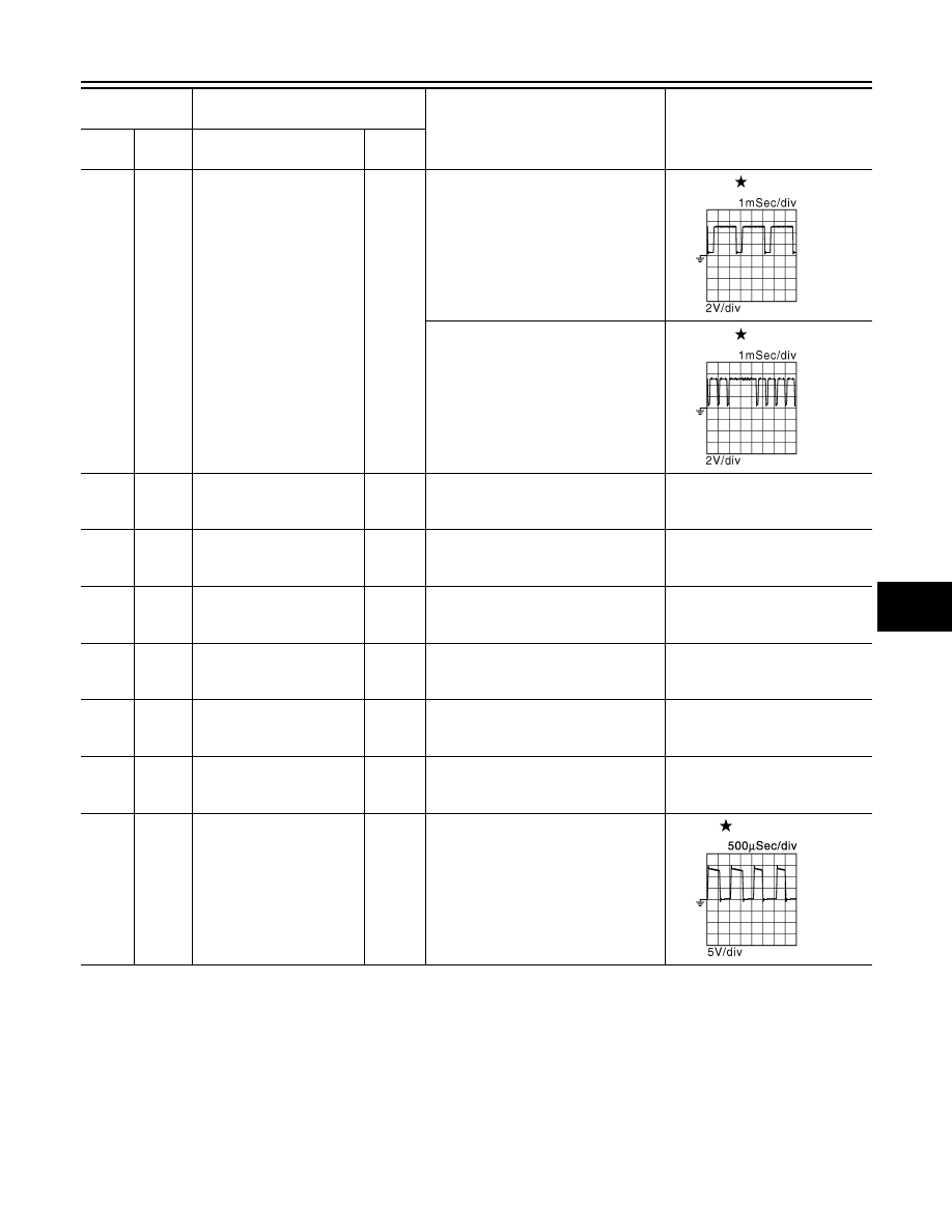
Crankshaft position sensor
Input
[Engine is running]
• Warm-up condition
• Idle speed
NOTE:
The pulse cycle changes depending
on rpm at idle
4.0 - 5.0 V
[Engine is running]
• Engine speed: 2,000 rpm
4.0 - 5.0 V
40
(R)
—
Sensor ground
[Throttle position sensor
(bank 1)]
—
—
—
43
(G)
48
(W)
Sensor power supply
[Throttle position sensor
(bank 2)]
—
[Ignition switch: ON]
5 V
44
(B)
40
(R)
Sensor power supply
[Throttle position sensor
(bank 1)]
—
[Ignition switch: ON]
5 V
46
(R)
47
(Y)
Sensor power supply
[Crankshaft position sen-
sor]
—
[Ignition switch: ON]
5 V
47
(Y)
—
Sensor ground
[Crankshaft position sen-
sor]
—
—
—
48
(W)
—
Sensor ground
[Throttle position sensor
(bank 2)]
—
—
—
49
(L)
128
(B)
Throttle control motor
(Close) (bank 2)
Output
[Ignition switch: ON]
• Engine stopped
• Selector lever: D
• Accelerator pedal: In the middle of
releasing operation
0 - 14 V
Terminal No.
(Wire color)
Description
Condition
Value
(Approx.)
+
-–
Signal name
Input/
Output
JMBIA0041GB
JMBIA0042GB
JMBIA0033GB
HAC-114
< ECU DIAGNOSIS INFORMATION >
[AUTOMATIC AIR CONDITIONER]
ECM
50
(V)
128
(B)
Throttle control motor
(Open) (bank 2)
Output
[Ignition switch: ON]
• Engine stopped
• Selector lever: D
• Accelerator pedal: Fully depressed
0 - 14 V
[Ignition switch: ON]
• Engine stopped
• Selector lever: D
• Accelerator pedal: Fully released
0 - 14 V
52
(R)
128
(B)
Throttle control motor relay
power supply (bank 2)
Input
[Ignition switch: ON]
BATTERY VOLTAGE
(11 - 14 V)
53
(P)
128
(B)
Ignition switch
Input
[Ignition switch: OFF]
0 V
[Ignition switch: ON]
BATTERY VOLTAGE
(11 - 14 V)
57
(L)
128
(B)
A/F sensor 1 (bank 1)
Input
[Ignition switch: ON]
2.2 V
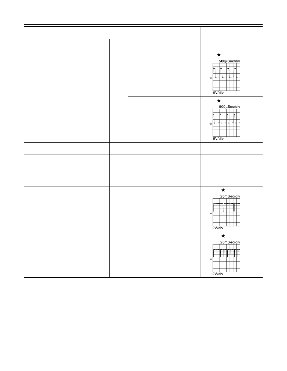
58
(Y)
88
(L)
Exhaust valve timing con-
trol position sensor (bank
1)
Input
[Engine is running]
• Warm-up condition
• Idle speed
NOTE:
The pulse cycle changes depending
on rpm at idle
4.0 - 5.0 V
[Engine is running]
• Warm-up condition
• Engine speed: 2,000 rpm
4.0 - 5.0 V
Terminal No.
(Wire color)
Description
Condition
Value
(Approx.)
+
-–
Signal name
Input/
Output
JMBIA0031GB
JMBIA0032GB
JMBIA0043GB
JMBIA0044GB
ECM
HAC-115
< ECU DIAGNOSIS INFORMATION >
[AUTOMATIC AIR CONDITIONER]
C
D
E
F
G
H
J
K
L
M
A
B
HAC
N
O
P
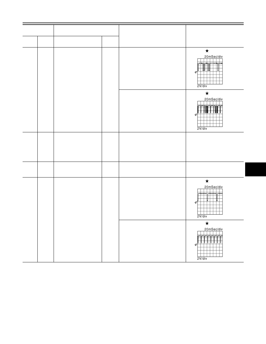
59
(O)
96
(B)
Camshaft position sensor
(bank 1)
Input
[Engine is running]
• Warm-up condition
• Idle speed
NOTE:
The pulse cycle changes depending
on rpm at idle
3.0 - 5.0 V
[Engine is running]
• Engine speed: 2,000 rpm
3.0 - 5.0 V
60
(R)
128
(B)
Sensor power supply
[Camshaft position sensor
(bank 1), Exhaust valve
timing control position sen-
sor (bank 1), Power steer-
ing pressure sensor]
—
[Ignition switch: ON]
5 V
61
(R)
128
(B)
A/F sensor 1 (bank 1)
Input
[Engine is running]
• Warm-up condition
• Engine speed: 2,000 rpm
1.8 V
Output voltage varies with air fuel
ratio.
62
(G)
88
(L)
Exhaust valve timing con-
trol position sensor (bank
2)
Input
[Engine is running]
• Warm-up condition
• Idle speed
NOTE:
The pulse cycle changes depending
on rpm at idle
4.0 - 5.0 V
[Engine is running]
• Warm-up condition
• Engine speed: 2,000 rpm
4.0 - 5.0 V
Terminal No.
(Wire color)
Description
Condition
Value
(Approx.)
+
-–
Signal name
Input/
Output
JMBIA0045GB
JMBIA0046GB
JMBIA0043GB
JMBIA0044GB
HAC-116
< ECU DIAGNOSIS INFORMATION >
[AUTOMATIC AIR CONDITIONER]
ECM
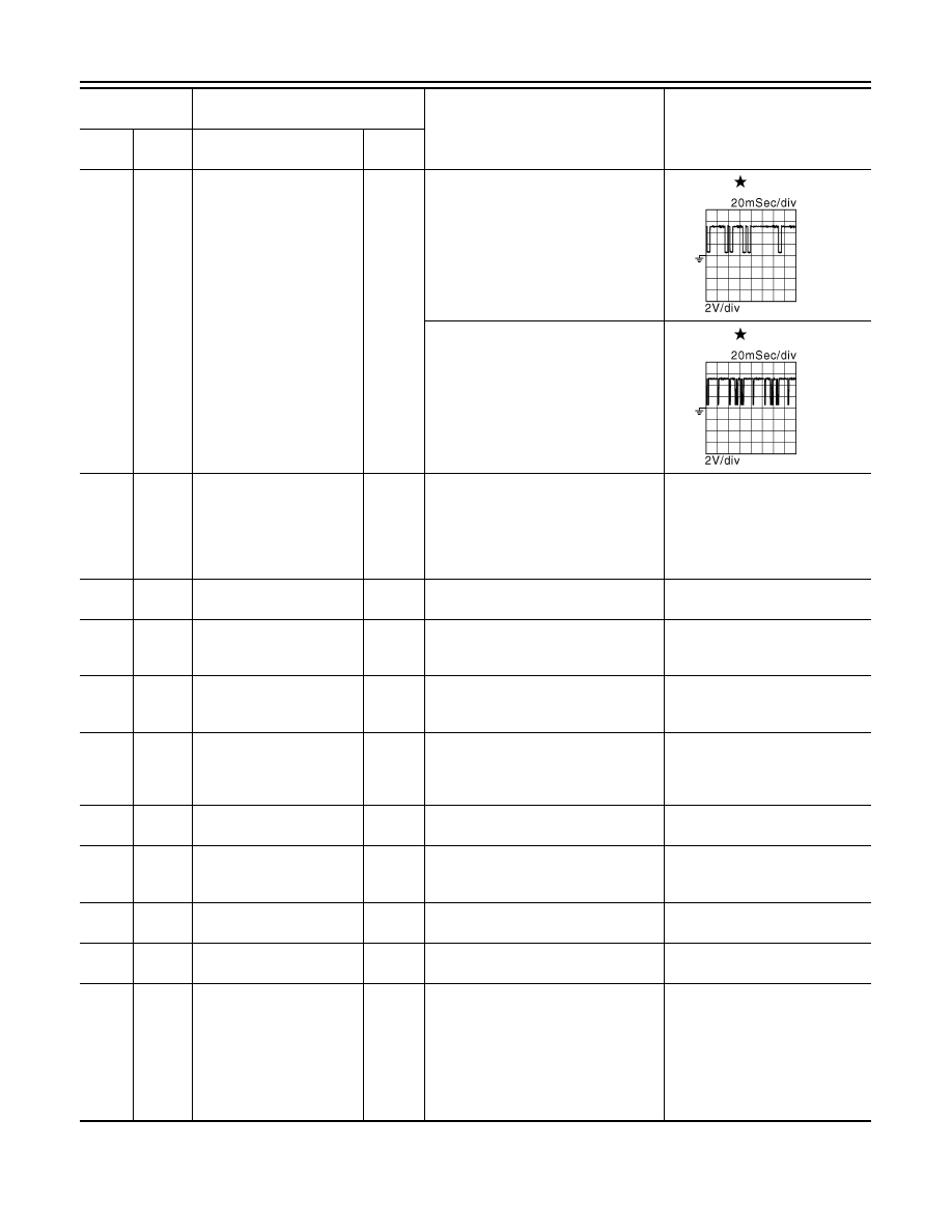
63
(SB)
128
(B)
Camshaft position sensor
(bank 2)
Input
[Engine is running]
• Warm-up condition
• Idle speed
NOTE:
The pulse cycle changes depending
on rpm at idle
3.0 - 5.0 V
[Engine is running]
• Engine speed: 2,000 rpm
3.0 - 5.0 V
64
(W)
128
(B)
Sensor power supply
[Camshaft position sensor
(bank 2), Exhaust valve
timing control position sen-
sor (bank 2), Battery cur-
rent sensor]
—
[Ignition switch: ON]
5 V
65
(V)
128
(B)
A/F sensor 1 (bank 2)
Input
[Ignition switch: ON]
2.2 V
66
(LG)
128
(B)
A/F sensor 1 (bank 2)
Input
[Engine is running]
• Warm-up condition
• Engine speed: 2,000 rpm
1.8 V
Output voltage varies with air fuel
ratio.
67
(P)
68
(LG)
Intake air temperature sen-
sor (bank 1)
Input
[Engine is running]
0 - 4.8 V
Output voltage varies with intake
air temperature.
68
(LG)
—
Sensor ground
[Mass air flow sensor (bank
1), Intake air temperature
sensor (bank 1)]
—
—
—
69
(W)
72
(B/W)
Knock sensor (bank 2)
Input
[Engine is running]
• Idle speed
2.5 V*
1
71
(Y)
84
(B)
Engine coolant tempera-
ture sensor
Input
[Engine is running]
0 - 4.8 V
Output voltage varies with engine
coolant temperature.
72
(B/W)
—
Sensor ground
(Knock sensor)
—
—
—
73
(W)
72
(B/W)
Knock sensor (bank 1)
Input
[Engine is running]
• Idle speed
2.5 V*
1
76
(W)
84
(B)
Heated oxygen sensor 2
(bank 1)
Input
[Engine is running]
• Revving engine from idle to 3,000
rpm quickly after the following condi-
tions are met
- Engine: after warming up
- Keeping the engine speed between
3,500 and 4,000 rpm for 1 minute
and at idle for 1 minute under no load
0 - 1.0 V
Terminal No.
(Wire color)
Description
Condition
Value
(Approx.)
+
-–
Signal name
Input/
Output
JMBIA0045GB
JMBIA0046GB
Нет комментариевНе стесняйтесь поделиться с нами вашим ценным мнением.
Текст