Infiniti FX35, FX50 (S51). Manual — part 1794
STARTING SYSTEM
STR-7
< SYSTEM DESCRIPTION >
C
D
E
F
G
H
I
J
K
L
M
A
STR
N
P
O
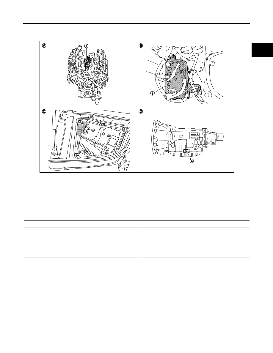
VK50VE : Component Parts Location
INFOID:0000000005245523
Component Description
INFOID:0000000005245524
1.
Starter motor
2.
BCM
3.
IPDM E/R
4.
TCM
A.
Engine
B.
Dash side lower (Passenger side)
C.
Engine room dash panel (RH)
D.
Inside of A/T (built into A/T)
JPBIA2375ZZ
Component part
Description
TCM
TCM supplies power to the starter relay and starter control relay
inside IPDM E/R when the selector lever is shifted to the P or N
position.
BCM
BCM controls the starter relay inside IPDM E/R.
IPDM E/R
CPU inside IPDM E/R controls the starter control relay.
Starter motor
The starter motor plunger closes and the motor is supplied with
battery power, which in turn cranks the engine, when the “S” ter-
minal is supplied with electric power.

STR-8
< DTC/CIRCUIT DIAGNOSIS >
B TERMINAL CIRCUIT
DTC/CIRCUIT DIAGNOSIS
B TERMINAL CIRCUIT
Description
INFOID:0000000005245525
The “B” terminal is constantly supplied with battery power.
Diagnosis Procedure
INFOID:0000000005245526
CAUTION:
Perform diagnosis under the condition that engine cannot start by the following procedure.
1.
Remove fuel pump fuse.
2.
Crank or start the engine (where possible) until the fuel pressure is released.
1.
CHECK “B” TERMINAL CIRCUIT
1.
Turn ignition switch OFF.
2.
Check that starter motor “B” terminal connection is clean and tight.
3.
Check voltage between starter motor “B” terminal and ground.
Is the inspection result normal?
YES
>> GO TO 2.
NO
>> Check harness between battery and starter motor for open circuit.
2.
CHECK BATTERY CABLE CONNECTION STATUS (VOLTAGE DROP TEST)
1.
Shift A/T selector lever to “P” or “N” position.
2.
Check voltage between battery positive terminal and starter motor “B” terminal.
Is the inspection result normal?
YES
>> GO TO 3.
NO
>> Check harness between the battery and the starter motor for poor continuity.
3.
CHECK GROUND CIRCUIT STATUS (VOLTAGE DROP TEST)
1.
Shift A/T selector lever to “P” or “N” position.
2.
Check voltage between starter motor case and battery negative terminal.
Is the inspection result normal?
YES
>> “B” terminal circuit is OK. Further inspection is necessary. Refer to
.
NO
>> Check the starter motor case and ground for poor continuity.
Terminals
Voltage (Approx.)
(+)
(–)
Starter motor “B” terminal
Terminal
E204 (VQ35HR)
E206 (VK50VE)
2 Ground
Battery
voltage
Terminals
Condition
Voltage (Approx.)
(+)
(–)
Starter motor
“B” terminal
Terminal
Battery positive terminal
E204 (VQ35HR)
E206 (VK50VE)
2
When the ignition switch is
in START position
Less than
0.5 V
Terminals
Condition
Voltage (Approx.)
(+)
(–)
Starter motor case
Battery negative terminal
When the ignition switch is in
START position
Less than 0.2 V

S CONNECTOR CIRCUIT
STR-9
< DTC/CIRCUIT DIAGNOSIS >
C
D
E
F
G
H
I
J
K
L
M
A
STR
N
P
O
S CONNECTOR CIRCUIT
Description
INFOID:0000000005245527
The starter motor magnetic switch is supplied with power when the ignition switch is turned to the START posi-
tion while the selector lever is in the P or N position.
Diagnosis Procedure
INFOID:0000000005245528
CAUTION:
Perform diagnosis under the condition that engine cannot start by the following procedure.
1.
Remove fuel pump fuse.
2.
Crank or start the engine (where possible) until the fuel pressure is released.
1.
CHECK “S” CONNECTOR CIRCUIT
1.
Turn ignition switch OFF.
2.
Disconnect starter motor connector.
3.
Shift A/T selector lever to “P” or “N” position.
4.
Check voltage between starter motor harness connector and ground.
Is the inspection result normal?
YES
>> “S” connector circuit is OK. Further inspection is necessary. Refer to
.
NO
>> GO TO 2.
2.
CHECK HARNESS CONTINUITY (OPEN CIRCUIT)
1.
Disconnect IPDM E/R connector.
2.
Check continuity between starter motor harness connector and IPDM E/R harness connector.
Is the inspection result normal?
YES
>> Further inspection is necessary. Refer to
.
NO
>> Repair the harness.
Terminals
Condition
Voltage (Approx.)
(+)
(–)
Starter motor har-
ness connector
Terminal
F52 (VQ35HR)
F55 (VK50VE)
1 Ground
When the ignition switch is in
START position
Battery voltage
Starter motor harness connector
IPDM E/R harness connector
Continuity
Connector No.
Terminal No.
Connector No.
Terminal No.
F52 (VQ35HR)
F55 (VK50VE)
1
E7
80
Existed
STR-10
< DTC/CIRCUIT DIAGNOSIS >
STARTING SYSTEM
STARTING SYSTEM
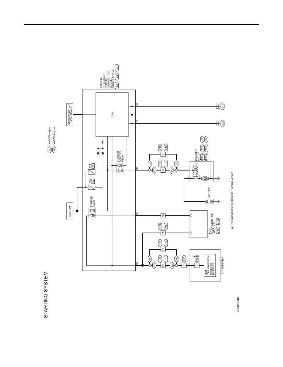
Wiring Diagram - STARTING SYSTEM -
INFOID:0000000005245529
JCBWM0710GB
Нет комментариевНе стесняйтесь поделиться с нами вашим ценным мнением.
Текст