Infiniti FX35, FX50 (S51). Manual — part 1017
EXL-64
< DTC/CIRCUIT DIAGNOSIS >
[XENON TYPE]
POWER SUPPLY AND GROUND CIRCUIT
Is the fuse fusing?
YES
>> Replace the blown fuse or fusible link after repairing the affected circuit if a fuse or fusible link is
blown.
NO
>> GO TO 2.
2.
CHECK POWER SUPPLY CIRCUIT
1.
Turn the ignition switch OFF.
2.
Disconnect IPDM E/R connector.
3.
Check voltage between IPDM E/R harness connector and ground.
Is the measurement value normal?
YES
>> GO TO 3.
NO
>> Repair harness or connector.
3.
CHECK GROUND CIRCUIT
Check continuity between IPDM E/R harness connectors and ground.
Does continuity exist?
YES
>> INSPECTION END
NO
>> Repair harness or connector.
AFS CONTROL UNIT
AFS CONTROL UNIT : Diagnosis Procedure
INFOID:0000000005244727
1.
FUSE INSPECTION
Check that the following fuses are not fusing.
Is the fuse fusing?
YES
>> Repair the applicable circuit. And then replace the fuse.
NO
>> GO TO 2.
2.
CHECK POWER SUPPLY CIRCUIT
1.
Turn the ignition switch OFF.
2.
Disconnect AFS control unit harness connector.
3.
Turn the ignition switch ON.
4.
Check voltage between the AFS control unit harness connector and the ground.
Signal name
Fuses and fusible link No.
Battery power supply
D
50
51
Terminals
Voltage
(Approx.)
(+)
(
−
)
IPDM E/R
Connector
Terminal
Ground
E4
1
Battery voltage
IPDM E/R
Ground
Continuity
Connector
Terminal
E5
12
Existed
E6
41
Signal name
Connection position
Fuse No.
Capacity
Ignition power supply
FUSE BLOCK (J/B)
3
10 A

POWER SUPPLY AND GROUND CIRCUIT
EXL-65
< DTC/CIRCUIT DIAGNOSIS >
[XENON TYPE]
C
D
E
F
G
H
I
J
K
M
A
B
EXL
N
O
P
Is the measurement value normal?
YES
>> GO TO 3.
NO
>> Repair the harness or connector.
3.
CHECK GROUND CIRCUIT
1.
Turn the ignition switch OFF.
2.
Check continuity between the AFS control unit harness connectors and the ground.
Does continuity exist?
YES
>> Repair the harness or connector.
NO
>> Power supply and ground circuit are normal.
Terminals
Voltage
(Approx.)
(+)
(
−
)
AFS control unit
Ground
Connector
Terminal
M16
1
Battery voltage
AFS control unit
Ground
Continuity
Connector
Terminal
M16
25
Existed
EXL-66
< DTC/CIRCUIT DIAGNOSIS >
[XENON TYPE]
EXTERIOR LAMP FUSE
EXTERIOR LAMP FUSE
Description
INFOID:0000000005244728
Fuse list
Diagnosis Procedure
INFOID:0000000005244729
1.
CHECK FUSE
Check that the following fuses are not fusing.
Is the fuse fusing?
YES
>> Repair the applicable circuit. And then replace the fuse.
NO
>> The fuse is normal.
Unit
Location
Fuse No.
Capacity
Headlamp HI (LH)
IPDM E/R
#54
10 A
Headlamp HI (RH)
IPDM E/R
#55
10 A
Headlamp LO (LH)
IPDM E/R
#56
15 A
Headlamp LO (RH)
IPDM E/R
#57
15 A
Front fog lamp
IPDM E/R
#58
15 A
• Parking lamp
• Front side marker lamp
IPDM E/R
#52
10 A
• Tail lamp
• Rear side marker lamp
• License plate lamp
• Each illumination
IPDM E/R
#53
10 A
Stop lamp
FUSE BLOCK (J/B)
#7
10 A
Back-up lamp
FUSE BLOCK (J/B)
#4
10 A
HEADLAMP (HI) CIRCUIT
EXL-67
< DTC/CIRCUIT DIAGNOSIS >
[XENON TYPE]
C
D
E
F
G
H
I
J
K
M
A
B
EXL
N
O
P
HEADLAMP (HI) CIRCUIT
Description
INFOID:0000000005244730
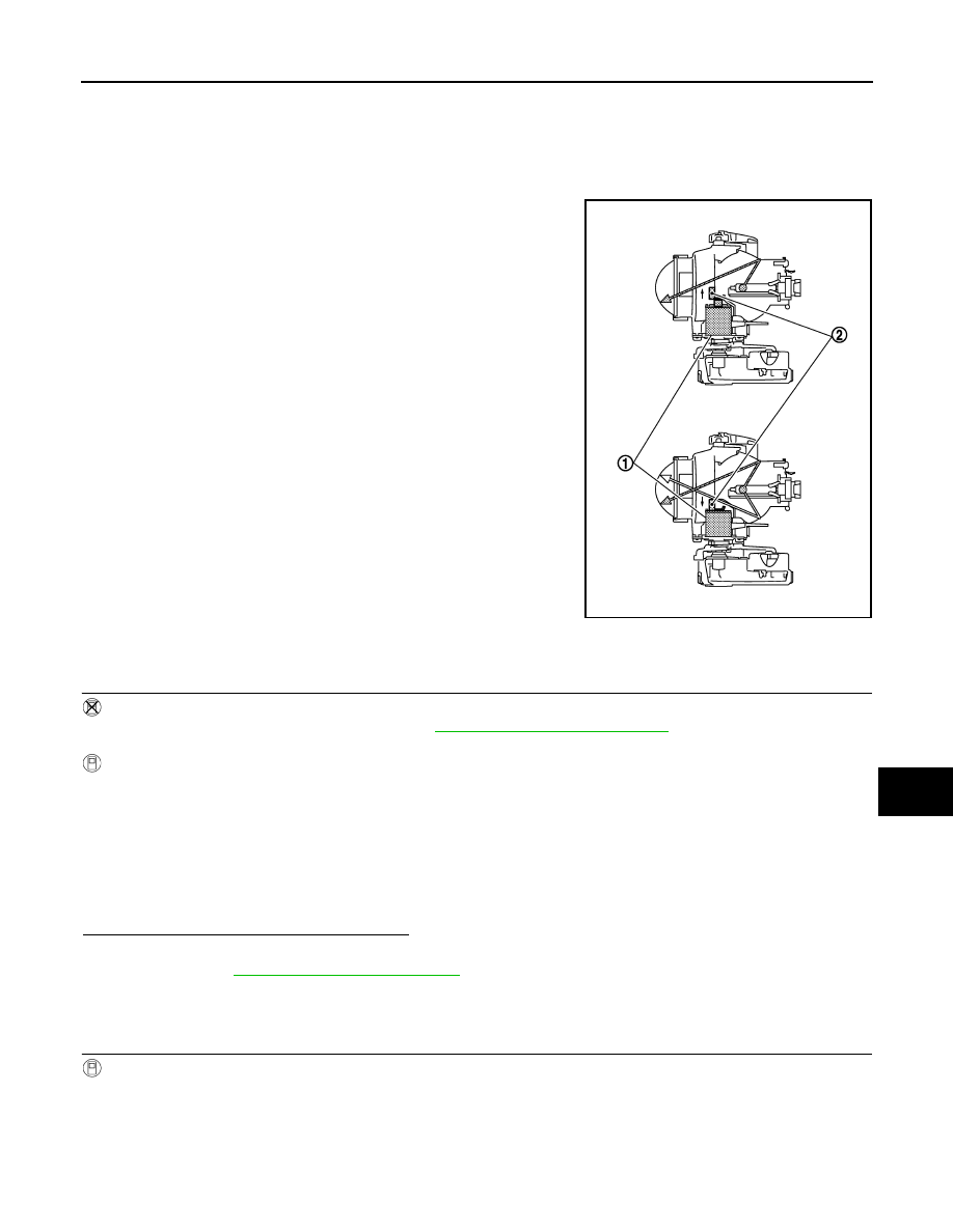
The high beam solenoid drives the mobile valve shade. And the mobile valve shade switches the high beam
and low beam of headlamp.
• When the headlamp high relay is turned ON, magnetic force is
applied to the high beam solenoid (1) by a current. The mobile
valve shade (2) is switched to the high beam position.
• When the headlamp high relay is turned OFF, the current stops.
The mobile valve shade returns to the low beam position automati-
cally.
Component Function Check
INFOID:0000000005244731
1.
CHECK HEADLAMP (HI) OPERATION
IPDM E/R AUTO ACTIVE TEST
1.
Activate IPDM E/R auto active test. Refer to
PCS-11, "Diagnosis Description"
.
2.
Check that the headlamp switches to the high beam.
CONSULT-III ACTIVE TEST
1.
Select "EXTERNAL LAMPS" of IPDM E/R active test item.
2.
With operating the test items, check that the headlamp switches to the high beam.
NOTE:
HI/LO is repeated 1 second each when using the IPDM E/R auto active test.
Does the headlamp switch to the high beam?
YES
>> Headlamp (HI) circuit is normal.
NO
>> Refer to
.
Diagnosis Procedure
INFOID:0000000005244732
1.
CHECK HEADLAMP (HI) OUTPUT VOLTAGE
CONSULT-III ACTIVE TEST
1.
Turn the ignition switch OFF.
2.
Disconnect the front combination lamp connector.
3.
Turn the ignition switch ON.
4.
Select "EXTERNAL LAMPS" of IPDM E/R active test item.
5.
With operating the test items, check the voltage between the IPDM E/R harness connector and the
ground.
JPLIA1158ZZ
Hi
: Headlamp switches to the high beam.
Off
: Headlamp OFF
Нет комментариевНе стесняйтесь поделиться с нами вашим ценным мнением.
Текст