Infiniti FX35, FX50 (S51). Manual — part 484

U1000 CAN COMM CIRCUIT
DLK-59
< DTC/CIRCUIT DIAGNOSIS >
C
D
E
F
G
H
I
J
L
M
A
B
DLK
N
O
P
DTC/CIRCUIT DIAGNOSIS
U1000 CAN COMM CIRCUIT
Description
INFOID:0000000005239521
CAN (Controller Area Network) is a serial communication line for real time applications. It is an on-vehicle mul-
tiplex communication line with high data communication speed and excellent error detectability. Modern vehi-
cles are equipped with many electronic control units, and each control unit shares information and links with
other control units during operation (not independent). In CAN communication, control units are connected by
2 communication lines (CAN H-line, CAN L-line) allowing a high rate of information transmission with less wir-
ing. Each control unit transmits/receives data but selectively reads required data only.
CAN Communication Signal Chart. Refer to
LAN-29, "CAN System Specification Chart"
DTC Logic
INFOID:0000000005239522
DTC DETECTION LOGIC
Diagnosis Procedure
INFOID:0000000005239523
1.
PERFORM SELF DIAGNOSTIC
1.
Turn ignition switch ON and wait for 2 seconds or more.
2.
Check “Self Diagnostic Result”.
Is “CAN COMM CIRCUIT” displayed?
YES
>> Refer to
LAN-20, "Trouble Diagnosis Flow Chart"
NO
>> Refer to
GI-36, "Intermittent Incident"
.
DTC
CONSULT-III display
description
DTC Detection Condition
Possible cause
U1000
CAN COMM CIRCUIT
When BCM cannot communicate CAN com-
munication signal continuously for 2 seconds
or more.
CAN communication system

DLK-60
< DTC/CIRCUIT DIAGNOSIS >
U1010 CONTROL UNIT (CAN)
U1010 CONTROL UNIT (CAN)
DTC Logic
INFOID:0000000005239524
DTC DETECTION LOGIC
Diagnosis Procedure
INFOID:0000000005239525
1.
REPLACE BCM
When DTC [U1010] is detected, replace BCM.
>> Replace BCM. Refer to
BCS-83, "Removal and Installation"
Special Repair Requirement
INFOID:0000000005239526
1.
REQUIRED WORK WHEN REPLACING BCM
Initialize control unit. Refer to CONSULT-III operation manual NATS-IVIS/NVIS.
>> Work end
DTC
CONSULT-III display de-
scription
DTC Detection Condition
Possible cause
U1010
CONTROL UNIT (CAN)
BCM detected internal CAN communication circuit malfunction.
BCM
B2621 INSIDE KEY ANTENNA 1
DLK-61
< DTC/CIRCUIT DIAGNOSIS >
C
D
E
F
G
H
I
J
L
M
A
B
DLK
N
O
P
B2621 INSIDE KEY ANTENNA 1
Description
INFOID:0000000005239527
Detects whether Intelligent Key is inside the vehicle.
Installed in the instrument center.
DTC Logic
INFOID:0000000005239528
DTC DETECTION LOGIC
DTC CONFIRMATION PROCEDURE
1.
PERFORM DTC CONFIRMATION PROCEDURE
1.
Perform inside key antenna (“INSIDE ANT DIAGNOSIS”) on “Work Support” in “INTELLIGENT KEY”.
2.
Perform “INTELLIGENT KEY” Self Diagnostic Result.
Is inside key antenna DTC detected?
YES
>> Refer to
.
NO
>> Inside key antenna (instrument center) is OK.
Diagnosis Procedure
INFOID:0000000005239529
1.
CHECK INSIDE KEY ANTENNA INPUT SIGNAL 1
1.
Turn ignition switch OFF.
2.
Check signal between BCM harness connector and ground using an oscilloscope.
Is the inspection result normal?
YES
>> GO TO 4.
NO
>> GO TO 2.
2.
CHECK INSIDE KEY ANTENNA CIRCUIT
1.
Disconnect BCM and inside key antenna connector.
DTC No.
Trouble diagnosis
name
DTC detecting condition
Possible cause
B2621
INSIDE ANTENNA 1
CIRCUIT
An excessively high or low voltage from inside an-
tenna is sent to BCM.
• Inside key antenna (instrument
center)
• Between BCM and Inside key an-
tenna (instrument center)
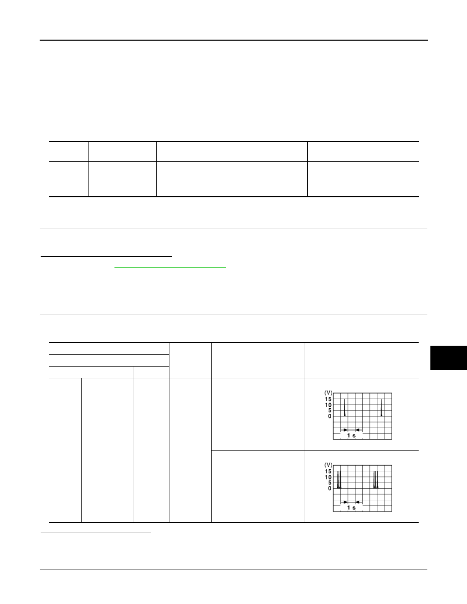
(+)
(–)
Condition
Signal
(Reference value)
BCM
Connector
Terminal
M122
Instrument cen-
ter
78, 79
Ground
Place Intelligent Key inside the
vehicle.
Place Intelligent Key outside
the vehicle.
JMKIA0062GB
JMKIA0063GB
DLK-62
< DTC/CIRCUIT DIAGNOSIS >
B2621 INSIDE KEY ANTENNA 1
2.
Check continuity between BCM harness connector and inside key antenna (instrument center) harness
connector.
3.
Check continuity between BCM harness connector and ground.
Is the inspection result normal?
YES
>> GO TO 3.
NO
>> Repair or replace harness.
3.
CHECK INSIDE KEY ANTENNA INPUT SIGNAL 2
1.
Replace inside key antenna (instrument center). (New antenna or another antenna)
2.
Connect BCM and inside key antenna (instrument center) connector.
3.
Check signal between BCM harness connector and ground using an oscilloscope.
Is the inspection result normal?
YES
>> Replace inside key antenna (instrument center). Refer to
NO
>> Replace BCM. Refer to
BCS-83, "Removal and Installation"
4.
CHECK INTERMITTENT INCIDENT
GI-36, "Intermittent Incident"
>> INSPECTION END
BCM
Inside key antenna (instrument center)
Continuity
Connector
Terminal
Connector
Terminal
M122
78
M131
2
Existed
79
1
BCM
Ground
Continuity
Connector
Terminal
M122
Instrument center
78
Not existed
79
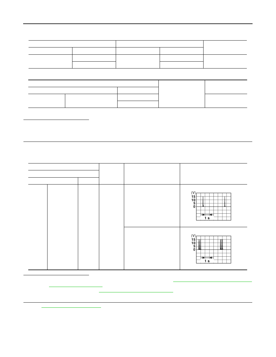
(+)
(–)
Condition
Signal
(Reference value)
BCM
Connector
Terminal
M122
Instrument cen-
ter
78, 79
Ground
Place Intelligent Key inside the
vehicle.
Place Intelligent Key outside
the vehicle.
JMKIA0062GB
JMKIA0063GB
Нет комментариевНе стесняйтесь поделиться с нами вашим ценным мнением.
Текст