Infiniti FX35, FX50 (S51). Manual — part 858

P100A, P100B VVEL SYSTEM
EC-973
< DTC/CIRCUIT DIAGNOSIS >
[VK50VE]
C
D
E
F
G
H
I
J
K
L
M
A
EC
N
P
O
YES
>> GO TO 9.
NO
>> INSPECTION END
9.
CHECK VVEL ACTUATOR SUB ASSEMBLY
EC-973, "Component Inspection (VVEL ACTUATOR SUB ASSEMBLY)"
.
Is the inspection result normal?
YES
>> GO TO 11.
NO
>> GO TO 10.
10.
REPLACE VVEL ACTUATOR SUB ASSEMBLY
1.
Replace VVEL actuator sub assembly.
2.
EC-974, "Special Repair Requirement"
>> INSPECTION END
11.
CHECK VVEL LADDER ASSEMBLY
Is the inspection result normal?
YES
>> GO TO 13.
NO
>> GO TO 12.
12.
REPLACE CYLINDER HEAD, VVEL LADDER ASSEMBLY AND VVEL ACTUATOR SUB ASSEMBLY
1.
Replace cylinder head, VVEL ladder assembly and VVEL actuator sub assembly.
2.
EC-974, "Special Repair Requirement"
>> INSPECTION END
13.
CHECK INTERMITTENT INCIDENT
GI-36, "Intermittent Incident"
.
>> INSPECTION END
Component Inspection (VVEL ACTUATOR MOTOR)
INFOID:0000000005237446
1.
CHECK VVEL ACTUATOR MOTOR
1.
Turn ignition switch OFF.
2.
Disconnect VVEL actuator motor harness connector.
3.
Check resistance between VVEL actuator motor terminals as per the following.
Is the inspection result normal?
YES
>> INSPECTION END
NO
>> GO TO 2.
2.
REPLACE VVEL ACTUATOR SUB ASSEMBLY
1.
Replace VVEL actuator sub assembly.
2.
EC-974, "Special Repair Requirement"
>> INSPECTION END
Component Inspection (VVEL ACTUATOR SUB ASSEMBLY)
INFOID:0000000005237447
1.
CHECK VVEL ACTUATOR SUB ASSEMBLY
1.
Turn ignition switch OFF.
VVEL actuator motor
Resistance
Terminal
1 and 2
16
Ω
or less

EC-974
< DTC/CIRCUIT DIAGNOSIS >
[VK50VE]
P100A, P100B VVEL SYSTEM
2.
Remove VVEL actuator sub assembly. Refer to
EM-228, "Disassembly and Assembly"
.
3.
Turn the ball screw shaft to check that it works smoothly.
Is the inspection result normal?
YES
>> INSPECTION END
NO
>> GO TO 2.
2.
REPLACE VVEL ACTUATOR SUB ASSEMBLY
1.
Replace VVEL actuator sub assembly.
2.
EC-974, "Special Repair Requirement"
>> INSPECTION END
Special Repair Requirement
INFOID:0000000005237448
1.
PERFORM VVEL CONTROL SHAFT POSITION SENSOR ADJUSTMENT
Refer to
EC-583, "VVEL CONTROL SHAFT POSITION SENSOR ADJUSTMENT : Special Repair Require-
>> GO TO 2.
2.
PERFORM IDLE AIR VOLUME LEARNING
EC-582, "IDLE AIR VOLUME LEARNING : Special Repair Requirement"
>> END
P1078, P1084 EVT CONTROL POSITION SENSOR
EC-975
< DTC/CIRCUIT DIAGNOSIS >
[VK50VE]
C
D
E
F
G
H
I
J
K
L
M
A
EC
N
P
O
P1078, P1084 EVT CONTROL POSITION SENSOR
Description
INFOID:0000000005237449
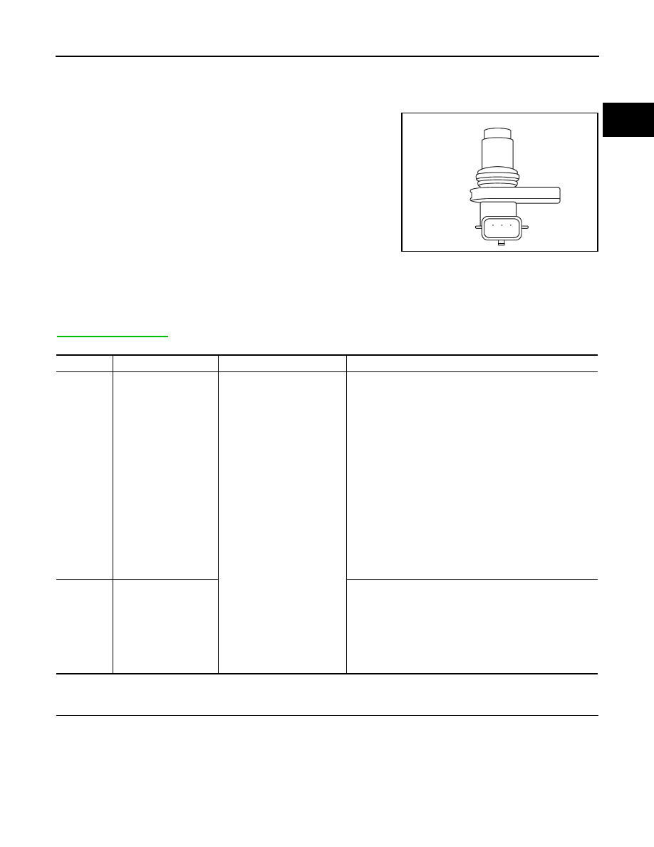
Exhaust valve timing control position sensor detects the protrution of
the signal plate installed to the exhaust camshaft front end.
This sensor signal is used for sensing a position of the exhaust cam-
shaft.
This sensor uses a Hall IC.
Based on the position of the exhaust camshaft, ECM controls
exhaust valve timing control solenoid valve to optimize the shut/open
timing of exhaust valve for the driving condition.
DTC Logic
INFOID:0000000005237450
DTC DETECTION LOGIC
NOTE:
If DTC P1078 is displayed with DTC P0643, first perform the trouble diagnosis for DTC P0643. Refer to
DTC CONFIRMATION PROCEDURE
1.
PRECONDITIONING
If DTC Confirmation Procedure has been previously conducted, always perform the following procedure
before conducting the next test.
1.
Turn ignition switch OFF and wait at least 10 seconds.
2.
Turn ignition switch ON.
3.
Turn ignition switch OFF and wait at least 10 seconds.
>> GO TO 2.
JMBIA0064ZZ
DTC No.
Trouble diagnosis name
DTC detecting condition
Possible cause
P1078
Exhaust valve timing
control position sensor
(bank 1) circuit
An excessively high or low
voltage from the sensor is
sent to ECM.
• Harness or connectors
[Exhaust valve timing control position sensor (bank 1) cir-
cuit is open or shorted)
(Accelerator pedal position sensor 2 circuit is shorted.)
(Battery current sensor circuit is shorted.)
[Camshaft position sensor (bank 1) circuit is shorted.]
(Crankshaft position sensor circuit is shorted.)
(EVAP control system pressure sensor circuit is shorted.)
(Manifold absolute pressure sensor circuit is shorted.)
• Exhaust valve timing control position sensor
• Accelerator pedal position sensor
• Battery current sensor
• Camshaft position sensor (bank 1)
• Crankshaft position sensor
• EVAP control system pressure sensor
• Manifold absolute pressure sensor
• Accumulation of debris to the signal pick-up portion of the
camshaft
P1084
Exhaust valve timing
control position sensor
(bank 2) circuit
• Harness or connectors
[Exhaust valve timing control position sensor (bank 2) cir-
cuit is open or shorted)
• Exhaust valve timing control position sensor (bank 2)
• Crankshaft position sensor
• Camshaft position sensor (bank 2)
• Accumulation of debris to the signal pick-up portion of the
camshaft

EC-976
< DTC/CIRCUIT DIAGNOSIS >
[VK50VE]
P1078, P1084 EVT CONTROL POSITION SENSOR
2.
PERFORM DTC CONFIRMATION PROCEDURE
1.
Start engine and let it idle for 10 seconds.
2.
Check 1st trip DTC.
Is 1st trip DTC detected?
YES
>> Go to
NO
>> INSPECTION END
Diagnosis Procedure
INFOID:0000000005237451
1.
CHECK GROUND CONNECTION
1.
Turn ignition switch OFF.
2.
Check ground connection M95, F33, F34. Refer to Ground Inspection in
.
Is the inspection result normal?
YES
>> GO TO 2.
NO
>> Repair or replace ground connection.
2.
CHECK EXHAUST VALVE TIMING CONTROL POSITION SENSOR POWER SUPPLY CIRCUIT-I
1.
Disconnect exhaust valve timing (EVT) control position sensor harness connector.
2.
Turn ignition switch ON.
3.
Check the voltage between exhaust valve timing control position sensor harness connector and ground.
Is the inspection result normal?
YES
>> GO TO 8.
NO-1
>> P1078: GO TO 3.
NO-2
>> P1084: Repair open circuit, short to ground or short to power in harness or connectors.
3.
CHECK EVT CONTROL POSITION SENSOR POWER SUPPLY CIRCUIT-II
1.
Turn ignition switch OFF.
2.
Disconnect ECM harness connector.
3.
Check the continuity between EVT control position sensor harness connector and ECM harness connec-
tor.
Is the inspection result normal?
YES
>> GO TO 4.
NO
>> Repair open circuit.
4.
CHECK SENSOR POWER SUPPLY CIRCUIT
Check harness for short to power and short to ground, between the following terminals.
DTC
EVT control position sensor
Ground
Voltage (V)
Bank
Connector
Terminal
P1078
1
F59
1
Ground
Approx. 5
P1084
2
F63
1
EVT control position sensor
ECM
Continuity
Bank
Connector
Terminal
Connector
Terminal
1
F59
1
F111
91
Existed
Нет комментариевНе стесняйтесь поделиться с нами вашим ценным мнением.
Текст