Infiniti FX35, FX50 (S51). Manual — part 859

P1078, P1084 EVT CONTROL POSITION SENSOR
EC-977
< DTC/CIRCUIT DIAGNOSIS >
[VK50VE]
C
D
E
F
G
H
I
J
K
L
M
A
EC
N
P
O
Is the inspection result normal?
YES
>> GO TO 5.
NO
>> Repair short to ground or short to power in harness or connectors.
5.
CHECK COMPONENTS
Check the following.
• Crankshaft position sensor (Refer to
EC-876, "Component Inspection"
• Camshaft position sensor (bank 1) (Refer to
EC-881, "Component Inspection"
• Battery current sensor (Refer to
EC-1025, "Component Inspection"
.)
• EVAP control system pressure sensor (Refer to
EC-917, "Component Inspection"
.)
• Manifold absolute pressure sensor (Refer to
EC-785, "Component Inspection"
Is the inspection result normal?
YES
>> GO TO 6.
NO
>> Replace malfunctioning component.
6.
CHECK APP SENSOR
EC-1076, "Component Inspection"
.
Is the inspection result normal?
YES
>> GO TO 14.
NO
>> GO TO 7.
7.
REPLACE ACCELERATOR PEDAL ASSEMBLY
1.
Replace accelerator pedal assembly.
2.
Go to
EC-1077, "Special Repair Requirement"
>> INSPECTION END
8.
CHECK EVT CONTROL POSITION SENSOR GROUND CIRCUIT FOR OPEN AND SHORT
1.
Turn ignition switch OFF.
2.
Disconnect ECM harness connector.
3.
Check the continuity between EVT control position sensor harness connector and ECM harness connec-
tor.
4.
Also check harness for short to ground and short to power.
Is the inspection result normal?
YES
>> GO TO 9.
NO
>> Repair open circuit, short to ground or short to power in harness or connectors.
ECM
Sensor
Connector
Terminal
Name
Connector
Terminal
F111
87
Crankshaft position sensor
F2
1
91
Camshaft position sensor (bank 1)
F84
1
EVT control position sensor (bank 1)
F59
1
95
Battery current sensor
E21
1
EVAP control system pressure sensor
B252
3
Manifold absolute pressure sensor
F65
1
M160
99
APP sensor (Wthout ICC)
E112
6
APP sensor (with ICC)
E116
3
DTC
EVT control position sensor
ECM
Continuity
Bank
Connector
Terminal
Connector
Terminal
P1078
1
F59
2
F111
58
Existed
P1084
2
F63
2
EC-978
< DTC/CIRCUIT DIAGNOSIS >
[VK50VE]
P1078, P1084 EVT CONTROL POSITION SENSOR
9.
CHECK EVT CONTROL POSITION SENSOR INPUT SIGNAL CIRCUIT FOR OPEN AND SHORT
1.
Check the continuity between EVT control position sensor harness connector and ECM harness connec-
tor.
2.
Also check harness for short to ground and short to power.
Is the inspection result normal?
YES
>> GO TO 10.
NO
>> Repair open circuit, short to ground or short to power in harness or connectors.
10.
CHECK EXHAUST VALVE TIMING CONTROL POSITION SENSOR
EC-978, "Component Inspection"
Is the inspection result normal?
YES
>> GO TO 11.
NO
>> Replace malfunctioning exhaust valve timing control position sensor.
11.
CHECK CRANKSHAFT POSITION SENSOR
EC-876, "Component Inspection"
Is the inspection result normal?
YES
>> GO TO 12.
NO
>> Replace crankshaft position sensor.
12.
CHECK CAMSHAFT POSITION SENSOR
EC-881, "Component Inspection"
Is the inspection result normal?
YES
>> GO TO 13.
NO
>> Replace malfunctioning camshaft position sensor.
13.
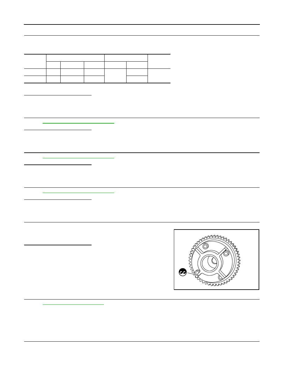
CHECK CAMSHAFT (EXH)
Check the following.
• Accumulation of debris to the signal plate of camshaft front end
• Chipping signal plate of camshaft front end
Is the inspection result normal?
YES
>> GO TO 14.
NO
>> Remove debris and clean the signal plate of camshaft
front end or replace camshaft.
14.
CHECK INTERMITTENT INCIDENT
GI-36, "Intermittent Incident"
>> INSPECTION END
Component Inspection
INFOID:0000000005237452
1.
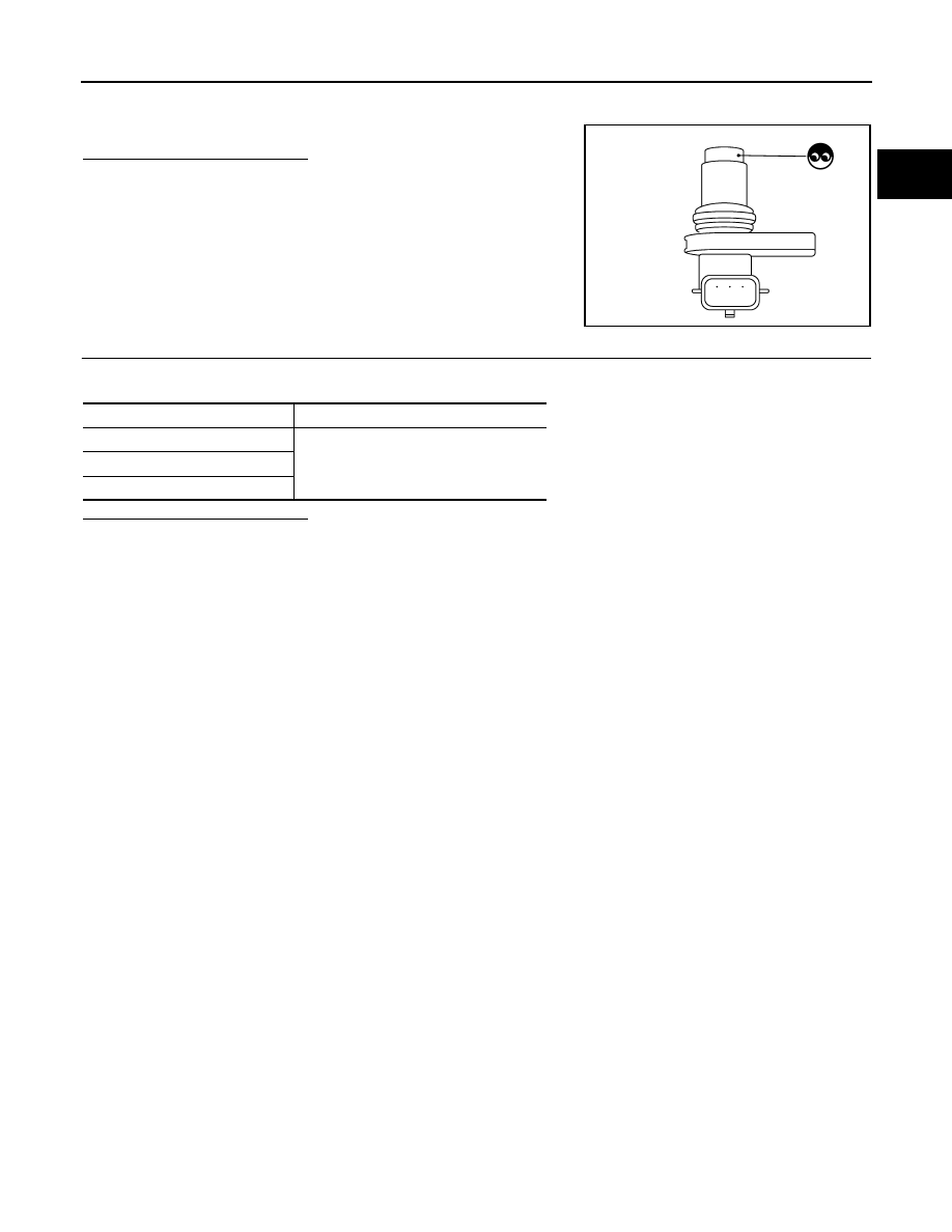
EXHAUST VALVE TIMING CONTROL POSITION SENSOR-I
1.
Turn ignition switch OFF.
2.
Disconnect exhaust valve timing control position sensor harness connector.
DTC
EVT control position sensor
ECM
Continuity
Bank
Connector
Terminal
Connector
Terminal
P1078
1
F59
3
F111
60
Existed
P1084
2
F63
3
64
JMBIA1571ZZ
P1078, P1084 EVT CONTROL POSITION SENSOR
EC-979
< DTC/CIRCUIT DIAGNOSIS >
[VK50VE]
C
D
E
F
G
H
I
J
K
L
M
A
EC
N
P
O
3.
Loosen the fixing bolt of the sensor.
4.
Remove the sensor.
5.
Visually check the sensor for chipping.
Is the inspection result normal?
YES
>> GO TO 2.
NO
>> Replace malfunctioning exhaust valve timing control
position sensor.
2.
EXHAUST VALVE TIMING CONTROL POSITION SENSOR-II
Check resistance exhaust valve timing control position sensor terminals as shown below.
Is the inspection result normal?
YES
>> INSPECTION END
NO
>> Replace malfunctioning exhaust valve timing control position sensor.
JMBIA0065ZZ
Terminals
Resistance
1 (+) - 2 (-)
Except 0 or
∞
Ω
[at 25
°
C (77
°
F)]
1 (+) - 3 (-)
2 (+) - 3 (-)

EC-980
< DTC/CIRCUIT DIAGNOSIS >
[VK50VE]
P1087, P1088 VVEL SYSTEM
P1087, P1088 VVEL SYSTEM
DTC Logic
INFOID:0000000005237453
DTC DETECTION LOGIC
NOTE:
If DTC P1087 or P1088 is displayed with DTC P1090 or P1093.
Perform the trouble diagnosis for DTC P1090 or P1093. Refer to
DTC No.
Trouble diagnosis name
DTC detecting condition
Possible cause
P1087
VVEL small event angle malfunction
(bank 1)
The event angle of VVEL control
shaft is always small.
• Harness or connectors
(VVEL actuator motor circuit is
open or shorted.)
• VVEL actuator motor
• VVEL actuator sub assembly
• VVEL ladder assembly
• VVEL control module
P1088
VVEL small event angle malfunction
(bank 2)
Нет комментариевНе стесняйтесь поделиться с нами вашим ценным мнением.
Текст