Infiniti FX35, FX50 (S51). Manual — part 1182

ECM
HAC-125
< ECU DIAGNOSIS INFORMATION >
[AUTOMATIC AIR CONDITIONER]
C
D
E
F
G
H
J
K
L
M
A
B
HAC
N
O
P
FAN DUTY
• Engine: Running
0 - 100%
ALT DUTY
• Engine: Idle
0 - 80%
BAT CUR SEN
• Engine speed: Idle
• Battery: Fully charged*
2
• Selector lever: P or N position
• A/C switch: OFF
• No load
Approx. 2,600 - 3,500 mV
A/F ADJ-B1
• Engine: Running
−
0.330 - 0.330
A/F ADJ-B2
• Engine: Running
−
0.330 - 0.330
TP SEN 1-B2
• Ignition switch: ON
(Engine stopped)
• Selector lever: D position
Accelerator pedal: Fully released
More than 0.36 V
Accelerator pedal: Fully depressed
Less than 4.75 V
TP SEN 2-B2*
1
• Ignition switch: ON
(Engine stopped)
• Selector lever: D position
Accelerator pedal: Fully released
More than 0.36 V
Accelerator pedal: Fully depressed
Less than 4.75 V
P/N POSI SW
• Ignition switch: ON
Selector lever: P or N
ON
Selector lever: Except above position
OFF
INT/A TEMP SE
• Ignition switch: ON
Indicates intake air temper-
ature
AC PRESS SEN
• Engine: Idle
• Both A/C switch and blower fan switch: ON (Compressor operates)
1.0 - 4.0 V
VTC DTY EX B1
• Engine: After warming up
• Selector lever: P or N position
• A/C switch: OFF
• No load
Idle
0% - 2%
Around 2,500 rpm while the engine speed
is rising
Approx. 0% - 70%
VTC DTY EX B2
• Engine: After warming up
• Selector lever: P or N position
• A/C switch: OFF
• No load
Idle
0 - 2%
Around 2,500 rpm while the engine speed
is rising
Approx. 0 - 70%
INT/V TIM (B1)
• Engine: After warming up
• Selector lever: P or N position
• A/C switch: OFF
• No load
Idle
−
5 - 5
°
CA
2,000 rpm
Approx. 0 - 30
°
CA
INT/V TIM (B2)
• Engine: After warming up
• Selector lever: P or N position
• A/C switch: OFF
• No load
Idle
−
5 - 5
°
CA
2,000 rpm
Approx. 0 - 30
°
CA
VVEL LEARN
• Ignition switch: OFF
→
ON
(After warming up)
VVEL learning has not been performed
yet.
YET
VVEL learning has already been per-
formed successfully.
DONE
VVEL SEN LEARN-B1
• VVEL learning has already been performed successfully
Approx. 0.30 - 0.80 V
VVEL SEN LEARN-B2
• VVEL learning has already been performed successfully
Approx. 0.30 - 0.80 V
VVEL POSITION SEN-
B1
• Engine: After warming up
• Selector lever: P or N position
• A/C switch: OFF
• No load
Idle
Approx. 0.25 - 1.40 V
When revving engine up to 2,000 rpm
quickly
Approx. 0.25 - 4.75 V
VVEL POSITION SEN-
B2
• Engine: After warming up
• Selector lever: P or N position
• Air conditioner switch: OFF
• No load
Idle
Approx. 0.25 - 1.40 V
When revving engine up to 2,000 rpm
quickly
Approx. 0.25 - 4.75 V
VVEL TIM-B1
• Engine: After warming up
• Selector lever: P or N position
• A/C switch: OFF
• No load
Idle
Approx. 0 - 20 deg
When revving engine up to 2,000 rpm
quickly
Approx. 0 - 90 deg
Monitor Item
Condition
Values/Status
HAC-126
< ECU DIAGNOSIS INFORMATION >
[AUTOMATIC AIR CONDITIONER]
ECM
*1: Accelerator pedal position sensor 2 signal and throttle position sensor 2 signal are converted by ECM internally. Thus, they differ
from ECM terminals voltage signal.
*2: Before measuring the terminal voltage, confirm that the battery is fully charged. Refer to
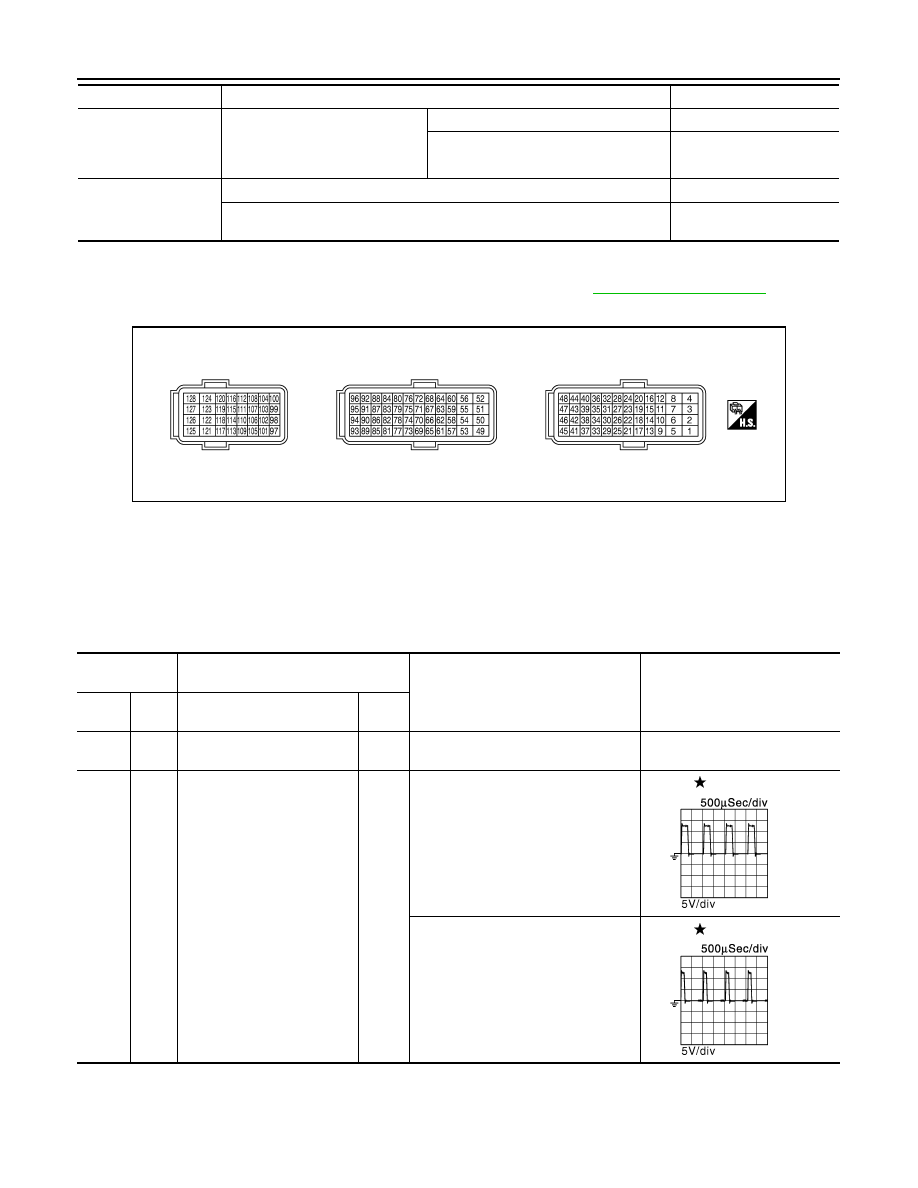
TERMINAL LAYOUT
PHYSICAL VALUES
NOTE:
• ECM is located behind the instrument assist lower panel. For this inspection, remove passenger side instru-
ment lower panel.
• Specification data are reference values and are measured between each terminals.
• Pulse signal is measured by CONSULT-III.
VVEL TIM-B2
• Engine: After warming up
• Selector lever: P or N position
• A/C switch: OFF
• No load
Idle
Approx. 0 - 20 deg
When revving engine up to 2,000 rpm
quickly
Approx. 0 - 90 deg
FPCM
• Engine: Cranking
HI
• Engine: Idle
• Engine coolant temperature: More than 10
°
C (50
°
F)
LOW
Monitor Item
Condition
Values/Status
JMBIA0070ZZ
Terminal No.
(Wire color)
Description
Condition
Value
(Approx.)
+
–
Signal name
Input/
Output
1
(P)
128
(B)
Throttle control motor power
supply (bank 2)
Input
[Ignition switch: ON]
BATTERY VOLTAGE
(11 - 14 V)
2
(L)
128
(B)
Throttle control motor (bank 2)
(Open)
Output
[Ignition switch: ON]
• Engine: Stopped
• Selector lever: D position
• Accelerator pedal: Fully depressed
0 - 14 V
[Ignition switch: ON]
• Engine: Stopped
• Selector lever: D position
• Accelerator pedal: Fully released
0 - 14 V
JMBIA0031GB
JMBIA0032GB

ECM
HAC-127
< ECU DIAGNOSIS INFORMATION >
[AUTOMATIC AIR CONDITIONER]
C
D
E
F
G
H
J
K
L
M
A
B
HAC
N
O
P
3
(Y)
128
(B)
A/F sensor 1 heater
(bank 1)
Output
[Engine is running]
• Warm-up condition
• Idle speed
(More than 140 seconds after start-
ing engine)
2.9 - 8.8 V
4
(G)
128
(B)
A/F sensor 1 heater
(bank 2)
Output
[Engine is running]
• Warm-up condition
• Idle speed
(More than 140 seconds after start-
ing engine)
2.9 - 8.8 V
5
(R)
128
(B)
Throttle control motor (bank 2)
(Close)
Output
[Ignition switch: ON]
• Engine: Stopped
• Selector lever: D position
• Accelerator pedal: In the middle of
releasing operation
0 - 14 V
6
(GR)
—
ECM ground
—
—
—
8
(W)
128
(B)
EVAP canister purge volume
control solenoid valve
Output
[Engine is running]
• Idle speed
• Accelerator pedal: Not depressed
even slightly, after engine starting
BATTERY VOLTAGE
(11 - 14 V)
[Engine is running]
• Engine speed: About 2,000 rpm
(More than 100 seconds after start-
ing engine)
BATTERY VOLTAGE
(11 - 14 V)
Terminal No.
(Wire color)
Description
Condition
Value
(Approx.)
+
–
Signal name
Input/
Output
JMBIA0030GB
JMBIA0030GB
JMBIA0033GB
JMBIA0039GB
JMBIA0040GB
HAC-128
< ECU DIAGNOSIS INFORMATION >
[AUTOMATIC AIR CONDITIONER]
ECM
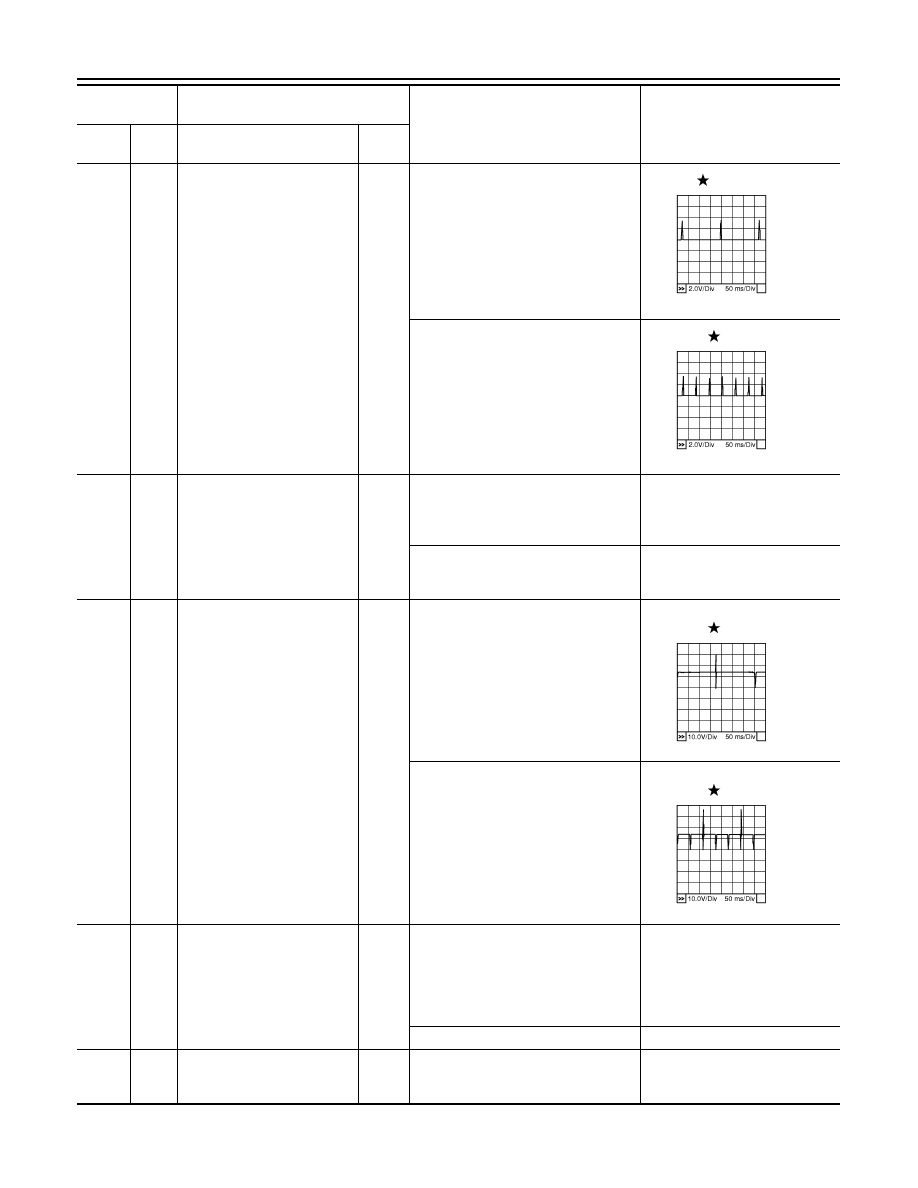
9
(G)
128
(B)
Ignition signal No. 2
Output
[Engine is running]
• Warm-up condition
• Idle speed
NOTE:
The pulse cycle changes depending
on rpm at idle
0 - 0.2 V
10
(Y)
Ignition signal No. 1
13
(V)
Ignition signal No. 3
14
(GR)
Ignition signal No. 4
18
(SB)
Ignition signal No. 5
[Engine is running]
• Warm-up condition
• Engine speed: 2,000 rpm
0.1 - 0.4 V
22
(LG)
Ignition signal No. 6
26
(L)
Ignition signal No. 7
30
(Y)
Ignition signal No. 8
15
(O)
128
(B)
ECM relay (Self shut-off)
Output
[Engine is running]
[Ignition switch: OFF]
• A few seconds after turning ignition
switch OFF
0 - 1.5 V
[Ignition switch: OFF]
• More than a few seconds after turn-
ing ignition switch OFF
BATTERY VOLTAGE
(11 - 14 V)
17
(R)
128
(B)
Fuel injector No. 3
Output
[Engine is running]
• Warm-up condition
• Idle speed
NOTE:
The pulse cycle changes depending
on rpm at idle
BATTERY VOLTAGE
(11 - 14 V)
21
(W)
Fuel injector No. 2
25
(P)
Fuel injector No. 1
29
(O)
Fuel injector No. 7
33
(G)
Fuel injector No. 8
[Engine is running]
• Warm-up condition
• Engine speed: 2,000 rpm
BATTERY VOLTAGE
(11 - 14 V)
37
(BR)
Fuel injector No. 4
41
(W)
Fuel injector No. 5
45
(V)
Fuel injector No. 6
19
(L)
128
(B)
Throttle control motor relay
Output
[Ignition switch: ON
→
OFF]
0 - 1.0 V
↓
BATTERY VOLTAGE
(11 - 14 V)
↓
0 V
[Ignition switch: ON]
0 - 1.0 V
23
(BR)
—
Sensor ground
(Engine coolant temperature
sensor)
—
—
—
Terminal No.
(Wire color)
Description
Condition
Value
(Approx.)
+
–
Signal name
Input/
Output
PBIB0044E
PBIB0045E
PBIB0042E
PBIB0043E
Нет комментариевНе стесняйтесь поделиться с нами вашим ценным мнением.
Текст