Infiniti FX35, FX50 (S51). Manual — part 1183

ECM
HAC-129
< ECU DIAGNOSIS INFORMATION >
[AUTOMATIC AIR CONDITIONER]
C
D
E
F
G
H
J
K
L
M
A
B
HAC
N
O
P
24
(Y)
23
(BR)
Engine coolant temperature
sensor
Input
[Engine is running]
0 - 4.8 V
Output voltage varies with engine
coolant temperature.
31
(B)
—
Sensor ground
(Heated oxygen sensor 2)
—
—
—
32
(W)
31
(B)
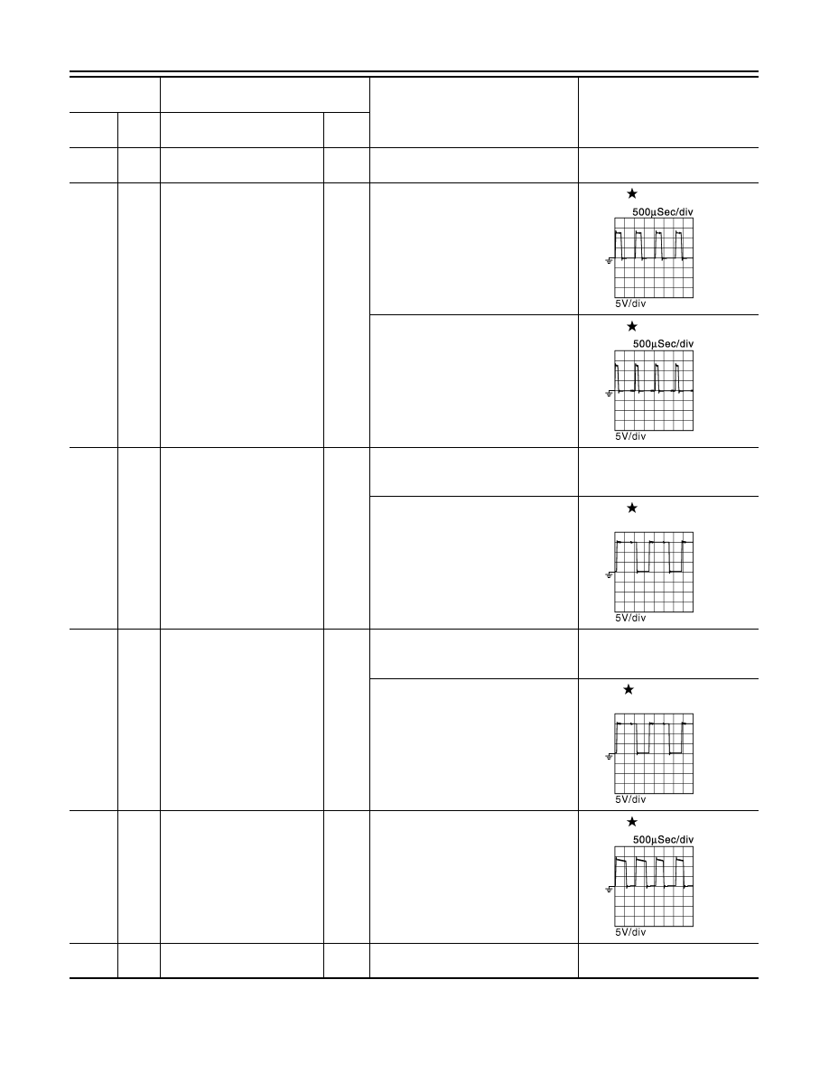
Heated oxygen sensor 2
(bank 1)
Input
[Engine is running]
• Revving engine from idle to 3,000
rpm quickly after the following condi-
tions are met
- Engine: after warming up
- Keeping the engine speed between
3,500 and 4,000 rpm for 1 minute
and at idle for 1 minute under no load
0 - 1.0 V
34
(V)
—
Sensor ground
(Engine oil temperature sen-
sor)
—
—
—
35
(B/W)
—
Sensor ground
(Knock sensor)
—
—
—
36
(LG)
31
(B)
Heated oxygen sensor 2
(bank 2)
Input
[Engine is running]
• Revving engine from idle to 3,000
rpm quickly after the following condi-
tions are met
- Engine: after warming up
- Keeping the engine speed between
3,500 and 4,000 rpm for 1 minute
and at idle for 1 minute under no load
0 - 1.0 V
38
(GR)
—
Sensor ground
[Mass air flow sensor (bank 2)]
—
—
—
39
(R)
34
(V)
Engine oil temperature sensor
Input
[Engine is running]
0 - 4.8 V
Output voltage varies with engine
oil temperature.
40
(W)
35
(B/W)
Knock sensor (bank 1)
Input
[Engine is running]
• Idle speed
2.5 V*
1
42
(B)
—
Sensor ground
[Mass air flow sensor (bank 1)/
Intake air temperature sensor]
—
—
—
43
(SB)
38
(GR)
Mass air flow sensor (bank 2)
Input
[Engine is running]
• Warm-up condition
• Idle speed
0.8 - 1.1 V
[Engine is running]
• Warm-up condition
• Engine speed: 2,500 rpm
1.3 - 1.6 V
44
(W)
35
(B/W)
Knock sensor (bank 2)
Input
[Engine is running]
• Idle speed
2.5 V*
1
47
(L)
42
(B)
Mass air flow sensor (bank 1)
Input
[Engine is running]
• Warm-up condition
• Idle speed
0.8 - 1.1 V
[Engine is running]
• Warm-up condition
• Engine speed: 2,500 rpm
1.3 - 1.6 V
48
(Y)
42
(B)
Intake air temperature sensor
Input
[Engine is running]
0 - 4.8 V
Output voltage varies with intake
air temperature.
Terminal No.
(Wire color)
Description
Condition
Value
(Approx.)
+
–
Signal name
Input/
Output
HAC-130
< ECU DIAGNOSIS INFORMATION >
[AUTOMATIC AIR CONDITIONER]
ECM
49
(V)
128
(B)
Throttle control motor power
supply (bank 1)
Input
[Ignition switch: ON]
BATTERY VOLTAGE
(11 - 14 V)
50
(G)
128
(B)
Throttle control motor (bank 1)
(Open)
Output
[Ignition switch: ON]
• Engine: Stopped
• Selector lever: D position
• Accelerator pedal: Fully depressed
0 - 14 V
[Ignition switch: ON]
• Engine: Stopped
• Selector lever: D position
• Accelerator pedal: Fully released
0 - 14 V
51
(O)
128
(B)
Intake valve timing control so-
lenoid valve (bank 1)
Output
[Engine is running]
• Warm-up condition
• Idle speed
BATTERY VOLTAGE
(11 - 14 V)
[Engine is running]
• Warm-up condition
• Engine speed: 2,000rpm
7 - 12 V
52
(L)
128
(B)
Intake valve timing control so-
lenoid valve (bank 2)
Output
[Engine is running]
• Warm-up condition
• Idle speed
BATTERY VOLTAGE
(11 - 14 V)
[Engine is running]
• Warm-up condition
• Engine speed: 2,000rpm
7 - 12V
53
(BR)
128
(B)
Throttle control motor (bank 1)
(Close)
Output
[Ignition switch: ON]
• Engine: Stopped
• Selector lever: D position
• Accelerator pedal: In the middle of
releasing operation
0 - 14 V
54
(B)
—
ECM ground
—
—
—
Terminal No.
(Wire color)
Description
Condition
Value
(Approx.)
+
–
Signal name
Input/
Output
JMBIA0031GB
JMBIA0032GB
JMBIA0038GB
JMBIA0038GB
JMBIA0033GB
ECM
HAC-131
< ECU DIAGNOSIS INFORMATION >
[AUTOMATIC AIR CONDITIONER]
C
D
E
F
G
H
J
K
L
M
A
B
HAC
N
O
P
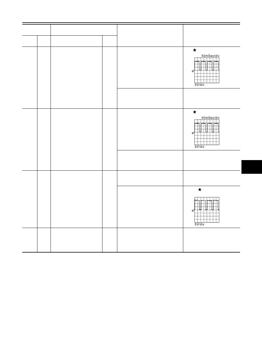
55
(P)
128
(B)
Heated oxygen sensor 2 heat-
er (bank 2)
Output
[Engine is running]
• Engine speed: Below 3,600 rpm after
the following conditions are met
- Engine: after warming up
- Keeping the engine speed between
3,500 and 4,000 rpm for 1 minute
and at idle for 1 minute under no load
10 V
[Ignition switch: ON]
• Engine: Stopped
[Engine is running]
• Engine speed: Above 3,600 rpm
BATTERY VOLTAGE
(11 - 14 V)
56
(R)
128
(B)
Heated oxygen sensor 2 heat-
er (bank 1)
Output
[Engine is running]
• Engine speed: Below 3,600 rpm after
the following conditions are met
- Engine: after warming up
- Keeping the engine speed between
3,500 and 4,000 rpm for 1 minute
and at idle for 1 minute under no load
10 V
[Ignition switch: ON]
• Engine: Stopped
[Engine is running]
• Engine speed: Above 3,600 rpm
BATTERY VOLTAGE
(11 - 14 V)
57
(Y)
128
(B)
Exhaust valve timing control
solenoid valve (bank 2)
Output
[Engine is running]
• Warm-up condition
• Idle speed
BATTERY VOLTAGE
(11 - 14 V)
[Engine is running]
• Warm-up condition
• Around 2,500 rpm while the engine
speed is rising
7 - 12 V
58
(B)
—
Sensor ground
[Camshaft position sensor
(bank 1)/ Exhaust valve timing
control position sensor (bank
1)]
—
—
—
Terminal No.
(Wire color)
Description
Condition
Value
(Approx.)
+
–
Signal name
Input/
Output
JMBIA0037GB
JMBIA0037GB
JMBIA0034GB
HAC-132
< ECU DIAGNOSIS INFORMATION >
[AUTOMATIC AIR CONDITIONER]
ECM
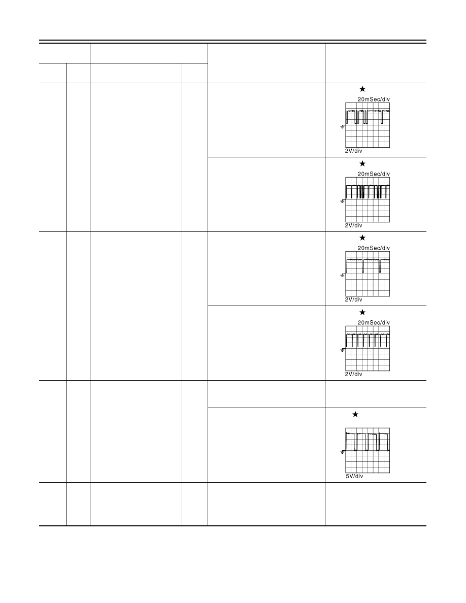
59
(W)
58
(B)
Camshaft position sensor
(bank 1)
Input
[Engine is running]
• Warm-up condition
• Idle speed
NOTE:
The pulse cycle changes depending
on rpm at idle
3.0 - 5.0 V
[Engine is running]
• Engine speed: 2,000 rpm
3.0 - 5.0 V
60
(G)
58
(B)
Exhaust valve timing control
position sensor (bank 1)
Input
[Engine is running]
• Warm-up condition
• Idle speed
NOTE:
The pulse cycle changes depending
on rpm at idle
4.0 - 5.0 V
[Engine is running]
• Warm-up condition
• Engine speed: 2,000 rpm
4.0 - 5.0 V
61
(G)
128
(B)
Exhaust valve timing control
solenoid valve (bank 1)
Output
[Engine is running]
• Warm-up condition
• Idle speed
BATTERY VOLTAGE
(11 - 14 V)
[Engine is running]
• Warm-up condition
• Around 2,500 rpm while the engine
speed is rising
7 - 12 V
62
(O)
—
Sensor ground
[Camshaft position sensor
(bank 2)/ Exhaust valve timing
control position sensor (bank
2)]
—
—
—
Terminal No.
(Wire color)
Description
Condition
Value
(Approx.)
+
–
Signal name
Input/
Output
JMBIA0045GB
JMBIA0046GB
JMBIA0043GB
JMBIA0044GB
JMBIA0034GB
Нет комментариевНе стесняйтесь поделиться с нами вашим ценным мнением.
Текст