Infiniti FX35, FX50 (S51). Manual — part 1849

SHIFT CHANGE CONTROL
TM-203
< SYSTEM DESCRIPTION >
[7AT: RE7R01B (VK50VE)]
C
E
F
G
H
I
J
K
L
M
A
B
TM
N
O
P
- Output speed sensor
- A/T fluid temperature sensor
- Transmission range switch
- Direct clutch solenoid valve
- High and low reverse clutch solenoid valve
- Input clutch solenoid valve
- Front brake solenoid valve
- Low brake solenoid valve
- Anti-interlock solenoid valve
- 2346 brake solenoid valve
- Line pressure solenoid valve
- Torque converter clutch solenoid valve
*1: Control valve with TCM is included in A/T assembly.
*2: With paddle shifter
Component Description
INFOID:0000000005250198
Name
Function
TCM
The TCM consists of a microcomputer and connectors for signal input and output and
for power supply. The TCM controls the A/T.
Output speed sensor
Input speed sensor 1
Input speed sensor 2
A/T fluid temperature sensor
Input clutch solenoid valve
Front brake solenoid valve
Direct clutch solenoid valve
High and low reverse clutch solenoid valve
Low brake solenoid valve
Anti-interlock solenoid valve
2346 brake solenoid valve
Line pressure solenoid valve
Torque converter clutch solenoid valve
ECM
BCM

TM-204
< SYSTEM DESCRIPTION >
[7AT: RE7R01B (VK50VE)]
SHIFT PATTERN CONTROL
SHIFT PATTERN CONTROL
ASC (ADAPTIVE SHIFT CONTROL)
ASC (ADAPTIVE SHIFT CONTROL) : System Diagram
INFOID:0000000005250199
ASC (ADAPTIVE SHIFT CONTROL) : System Description
INFOID:0000000005250200
INPUT/OUTPUT SIGNAL CHART
*: This signal is transmitted via CAN communication line.
SYSTEM DESCRIPTION
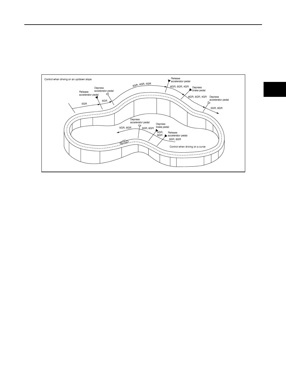
ASC (Adaptive Shift Control)
It automatically selects the shift pattern (such as road environment and driving style) suitable for the various
situations so as to allow the vehicle to be driven efficiently and smoothly.
For example. .
• When driving on an up/down slope
JSDIA1364GB
Sensor
Input signal to TCM
TCM function
Actuator
Input speed sensor 1, 2
Input speed
Shift pattern control
• High and low reverse
clutch solenoid valve
• Direct clutch solenoid
valve
• Input clutch solenoid valve
• Low brake solenoid valve
• 2346 brake solenoid valve
• Front brake solenoid valve
• Torque converter clutch so-
lenoid valve
• Line pressure solenoid
valve
• Anti-interlock solenoid
valve
Output speed sensor
Vehicle speed
A/T fluid temperature sensor
ATF temperature
ECM
Engine speed signal*
Accelerator pedal position signal*
Closed throttle position signal*
Engine and A/T integrated control signal
(engine torque)*
ABS actuator and electric unit
(control unit)
Side G sensor signal*
BCM
Stop lamp switch signal*
SHIFT PATTERN CONTROL
TM-205
< SYSTEM DESCRIPTION >
[7AT: RE7R01B (VK50VE)]
C
E
F
G
H
I
J
K
L
M
A
B
TM
N
O
P
ASC judges up/down slope according to engine torque data transmitted from the ECM and vehicle speed.
Fixing at 4GR, 5GR or 6GR on an up-slope prevents shift hunting and controls the vehicle to gain optimum
driving force. On a down-slope, automatic shift-down to 4GR, 5GR or 6GR controls to gain optimum engine
brake.
• When driving on a curve
TCM receives the side G sensor signal from the ABS actuator and electric unit (control unit). It locks to 4GR,
5GR or 6GR position in moderate cornering or to 3GR position in sharp cornering based on this signal. This
prevents any upshift and kickdown during cornering, maintaining smooth vehicle travel.
DS Mode
• Changes to the shift schedule that mainly utilizes the high engine speed zone when ASC is active.
• DS mode can be switched according to the following method.
- When the selector lever is in the “D” position, shifting the selector lever to manual shift gate enables switch-
ing to DS mode.
- When in DS mode, shifting the selector lever to the main gate enables to cancel DS mode.
- After switching to manual mode with paddle shifter, switching to DS mode can not be enabled even when the
selector lever is shifted to the manual gate. (With paddle shifter)
JSDIA1362GB
TM-206
< SYSTEM DESCRIPTION >
[7AT: RE7R01B (VK50VE)]
SHIFT PATTERN CONTROL
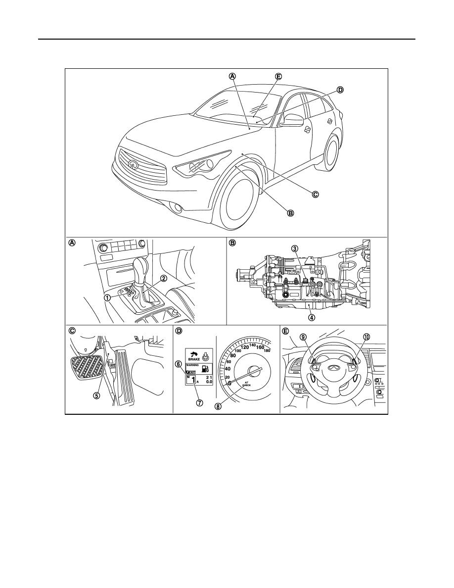
ASC (ADAPTIVE SHIFT CONTROL) : Component Parts Location
INFOID:0000000005520215
NOTE:
• The following components are included in A/T shift selector assembly.
- Manual mode select switch
- Manual mode position select switch
- Shift position switch
• The following components are included in control valve with TCM.
- TCM
- Input speed sensor 1, 2
1.
Selector lever position indicator
2.
A/T shift selector assembly
3.
A/T assembly connector
4.
Control valve with TCM
*1
5.
Accelerator pedal position sensor
6.
Manual mode indicator
7.
Shift position indicator
8.
A/T CHECK indicator lamp
9.
Paddle shifter (shift-down)
*2
10. Paddle shifter (shift-up)
*2
A.
Center console
B.
A/T assembly
C.
Accelerator pedal
D.
Combination meter
E.
Steering wheel
JSDIA0787ZZ
Нет комментариевНе стесняйтесь поделиться с нами вашим ценным мнением.
Текст