Infiniti FX35, FX50 (S51). Manual — part 1848
SHIFT CHANGE CONTROL
TM-199
< SYSTEM DESCRIPTION >
[7AT: RE7R01B (VK50VE)]
C
E
F
G
H
I
J
K
L
M
A
B
TM
N
O
P
SHIFT CHANGE CONTROL
System Diagram
INFOID:0000000005250195
System Description
INFOID:0000000005250196
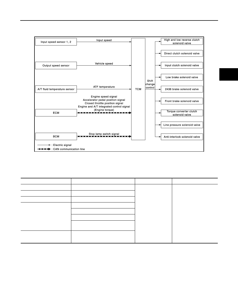
INPUT/OUTPUT SIGNAL CHART
*: This signal is transmitted via CAN communication line.
SYSTEM DESCRIPTION
The clutch pressure control solenoid is controlled by the signals from the switches and sensors. Thus, the
clutch pressure is adjusted to be appropriate to the engine load state and vehicle driving state. It becomes
JSDIA1346GB
Sensor
Input signal to TCM
TCM function
Actuator
Input speed sensor 1, 2
Input speed
Shift change control
• High and low reverse
clutch solenoid valve
• Direct clutch solenoid
valve
• Input clutch solenoid valve
• Low brake solenoid valve
• 2346 brake solenoid valve
• Front brake solenoid valve
• Torque converter clutch so-
lenoid valve
• Line pressure solenoid
valve
• Anti-interlock solenoid
valve
Output speed sensor
Vehicle speed
A/T fluid temperature sensor
ATF temperature
ECM
Engine speed signal*
Accelerator pedal position signal*
Closed throttle position signal*
Engine and A/T integrated control signal
(Engine torque)*
BCM
Stop lamp switch signal*
TM-200
< SYSTEM DESCRIPTION >
[7AT: RE7R01B (VK50VE)]
SHIFT CHANGE CONTROL
possible to finely control the clutch hydraulic pressure with high precision and a smoother shift change charac-
teristic is attained.
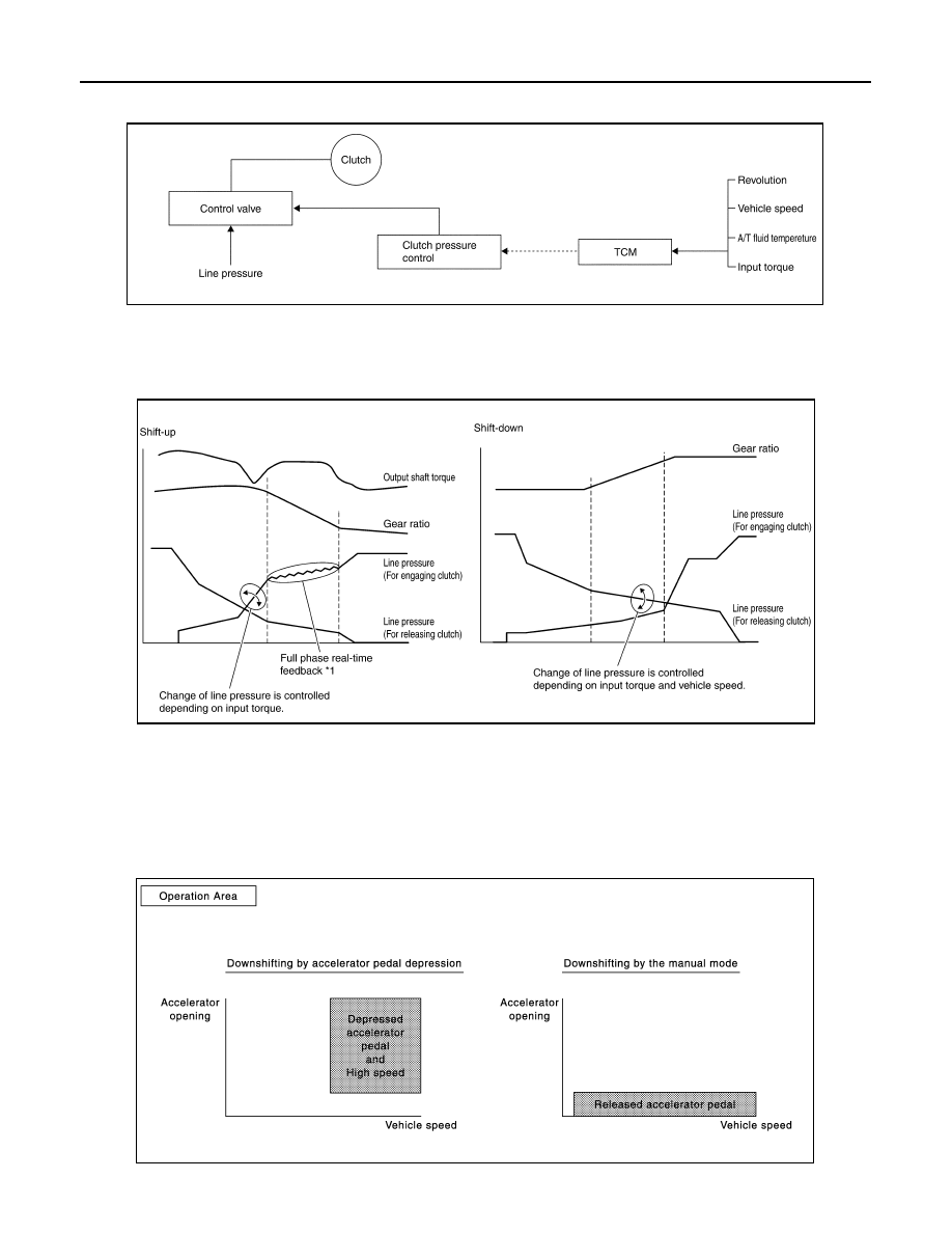
Shift Change
The clutch is controlled with the optimum timing and oil pressure by the engine speed, engine torque informa-
tion, etc.
Shift Change System Diagram
*1: Full phase real-time feedback control monitors movement of gear ratio at gear change, and controls oil
pressure in real-time to achieve the best gear ratio.
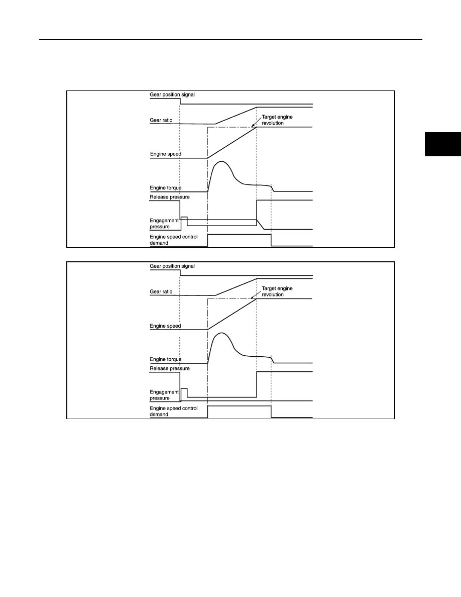
Blipping Control
This system makes transmission clutch engage readily by controlling (synchronizing) engine revolution
according to the (calculation of) engine revolution after shifting down.
• “BLIPPING CONTROL” functions.
- When downshifting by accelerator pedal depression.
- When downshifting by the manual mode.
PCIA0012E
PCIA0013E
JSDIA0826GB
SHIFT CHANGE CONTROL
TM-201
< SYSTEM DESCRIPTION >
[7AT: RE7R01B (VK50VE)]
C
E
F
G
H
I
J
K
L
M
A
B
TM
N
O
P
• TCM selects “BLIPPING CONTROL” or “NORMAL SHIFT CONTROL” according to the gear position, the
selector lever position, the engine torque and the speed when accelerating by pedal depression.
• Engine speed control demand signal is transmitted from TCM to ECM under “BLIPPING CONTROL”.
• ECM synchronizes the engine speed according to the engine speed control demand signal.
Downshifting by accelerator pedal depression
Downshifting by the manual mode
JSDIA0815GB
JSDIA0817GB
TM-202
< SYSTEM DESCRIPTION >
[7AT: RE7R01B (VK50VE)]
SHIFT CHANGE CONTROL
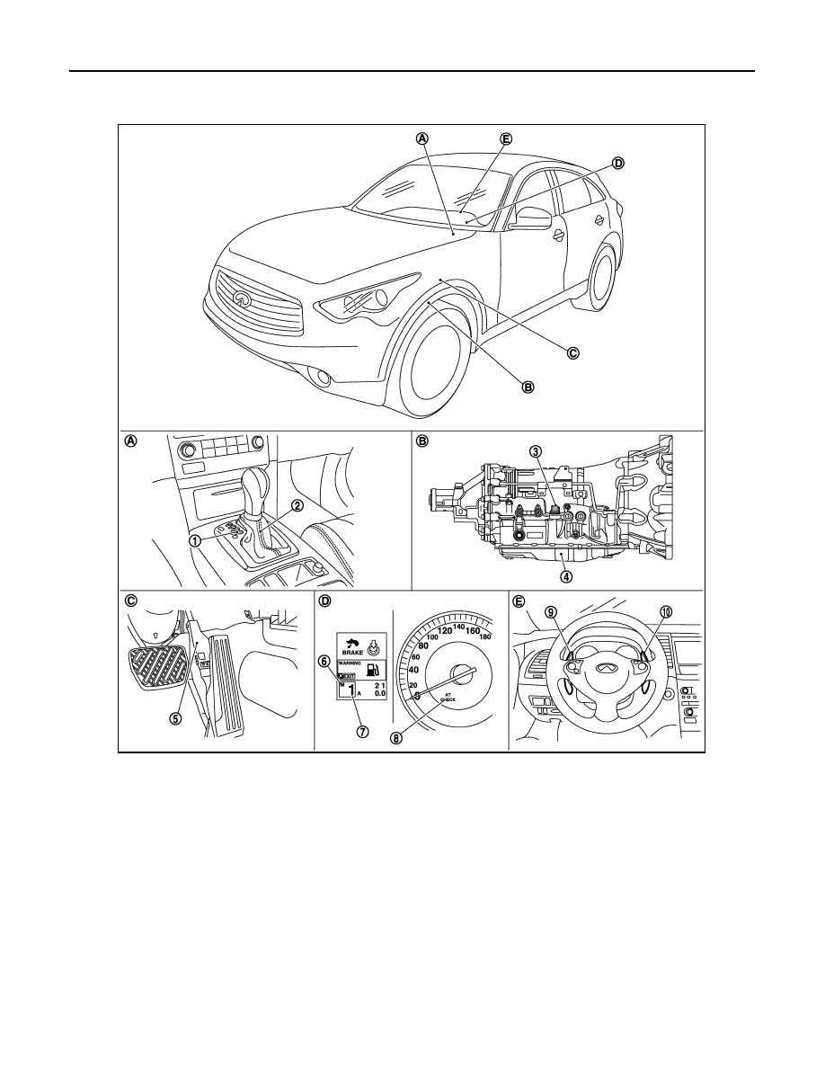
Component Parts Location
INFOID:0000000005520212
NOTE:
• The following components are included in A/T shift selector assembly.
- Manual mode select switch
- Manual mode position select switch
- Shift position switch
• The following components are included in control valve with TCM.
- TCM
- Input speed sensor 1, 2
1.
Selector lever position indicator
2.
A/T shift selector assembly
3.
A/T assembly connector
4.
Control valve with TCM
*1
5.
Accelerator pedal position sensor
6.
Manual mode indicator
7.
Shift position indicator
8.
A/T CHECK indicator lamp
9.
Paddle shifter (shift-down)
*2
10. Paddle shifter (shift-up)
*2
A.
Center console
B.
A/T assembly
C.
Accelerator pedal
D.
Combination meter
E.
Steering wheel
JSDIA0787ZZ
Нет комментариевНе стесняйтесь поделиться с нами вашим ценным мнением.
Текст