Infiniti FX35, FX50 (S51). Manual — part 992
EM-268
< UNIT DISASSEMBLY AND ASSEMBLY >
[VK50VE]
CYLINDER BLOCK
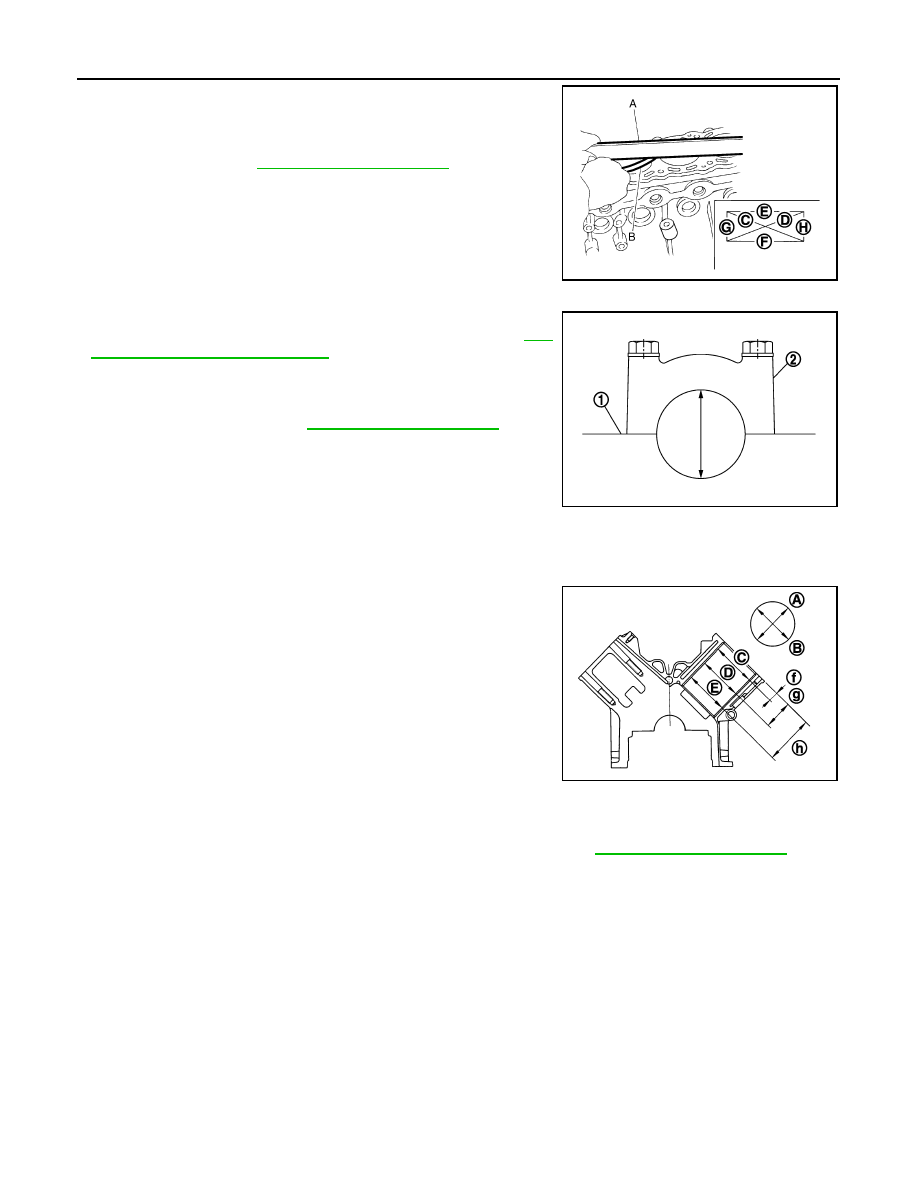
• Measure the distortion on the cylinder block upper face at some
different points in six directions (C, D, E, F, G and H) with a
straightedge (A) and a feeler gauge (B).
• If it exceeds the limit, replace cylinder block.
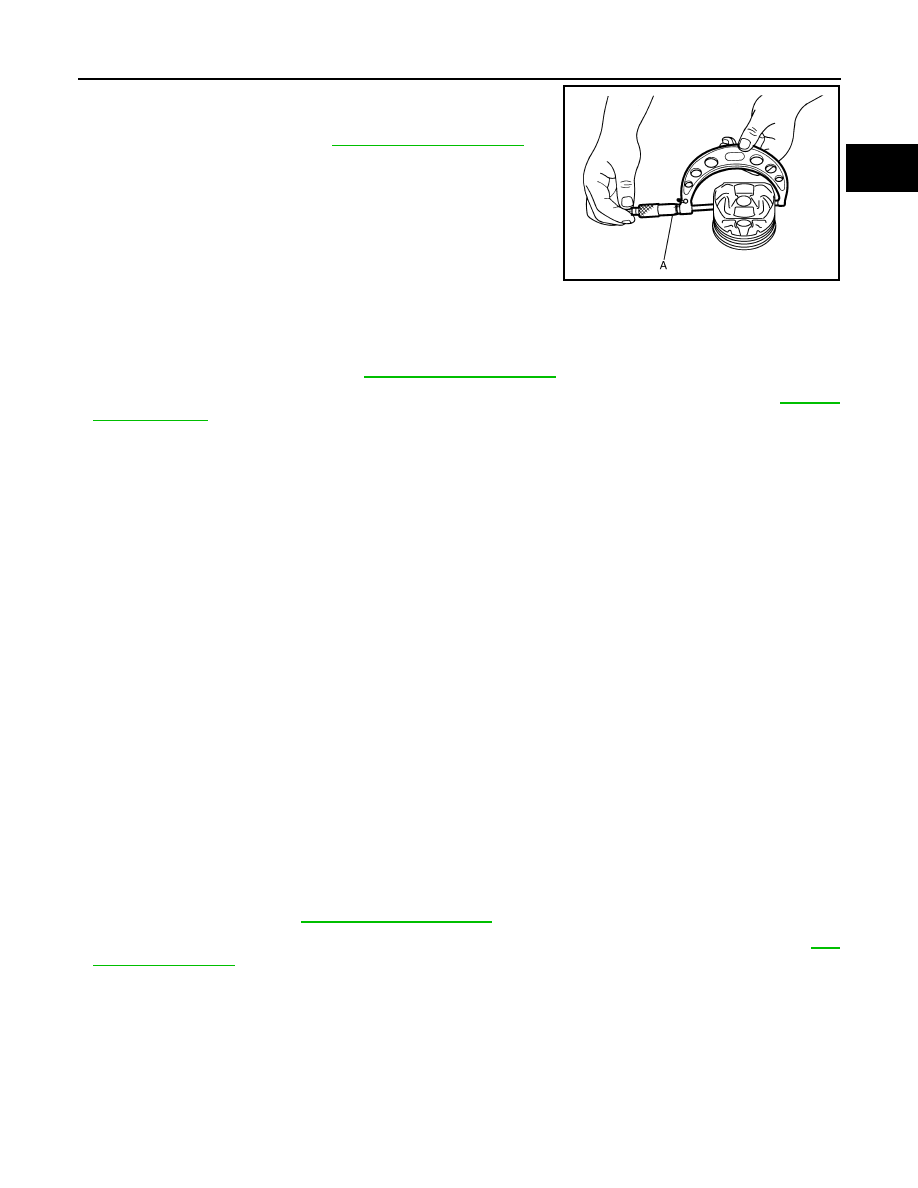
MAIN BEARING HOUSING INNER DIAMETER
• Install main bearing cap (2) without installing main bearings, and
tighten main bearing cap bolts to the specified torque. Refer to
256, "Disassembly and Assembly"
for the tightening procedure.
• Measure the inner diameter of main bearing housing with a bore
gauge.
• If out of the standard, replace cylinder block (1) and main bearing
cap as assembly.
NOTE:
Cylinder block cannot be replaced as a single part, because it is
machined together with main bearing cap.
PISTON TO CYLINDER BORE CLEARANCE
Cylinder Bore inner Diameter
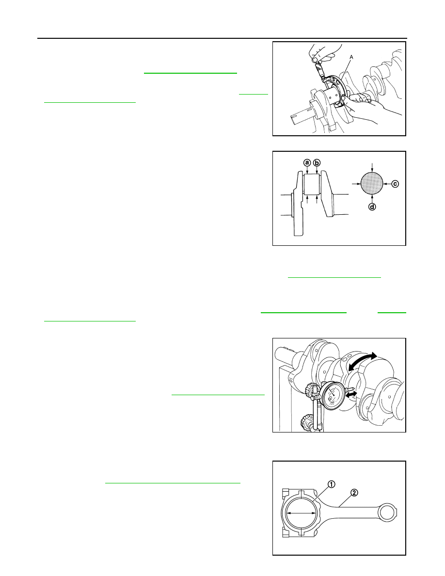
• Using a bore gauge, measure cylinder bore for wear, out-of-round
and taper at six different points on each cylinder. [(A) and (B) direc-
tions at (C), (D) and (E)] is in longitudinal direction of engine.
• If the measured value exceeds the limit, or if there are scratches and/or seizure on the cylinder inner wall,
hone or re-bore the inner wall.
• Oversize piston is provided. When using oversize piston, re-bore cylinder so that the clearance of the piston-
to-cylinder bore satisfies the standard.
CAUTION:
When using oversize piston, use oversize pistons for all cylinders with oversize piston rings.
Piston Skirt Diameter
Limit
: Refer to
JPBIA0224ZZ
Standard
: Refer to
JPBIA0225ZZ
f
: 10 mm (0.39 in)
g
: 60 mm (2.36 in)
h
: 120 mm (4.72 in)
JPBIA2279ZZ
Wear limit:
Refer to
.
Out-of-round (Difference between “A” and “B”):
Taper limit (Difference between “C” and “E”):
Oversize (O/S)
: 0.2 mm (0.008 in)
CYLINDER BLOCK
EM-269
< UNIT DISASSEMBLY AND ASSEMBLY >
[VK50VE]
C
D
E
F
G
H
I
J
K
L
M
A
EM
N
P
O
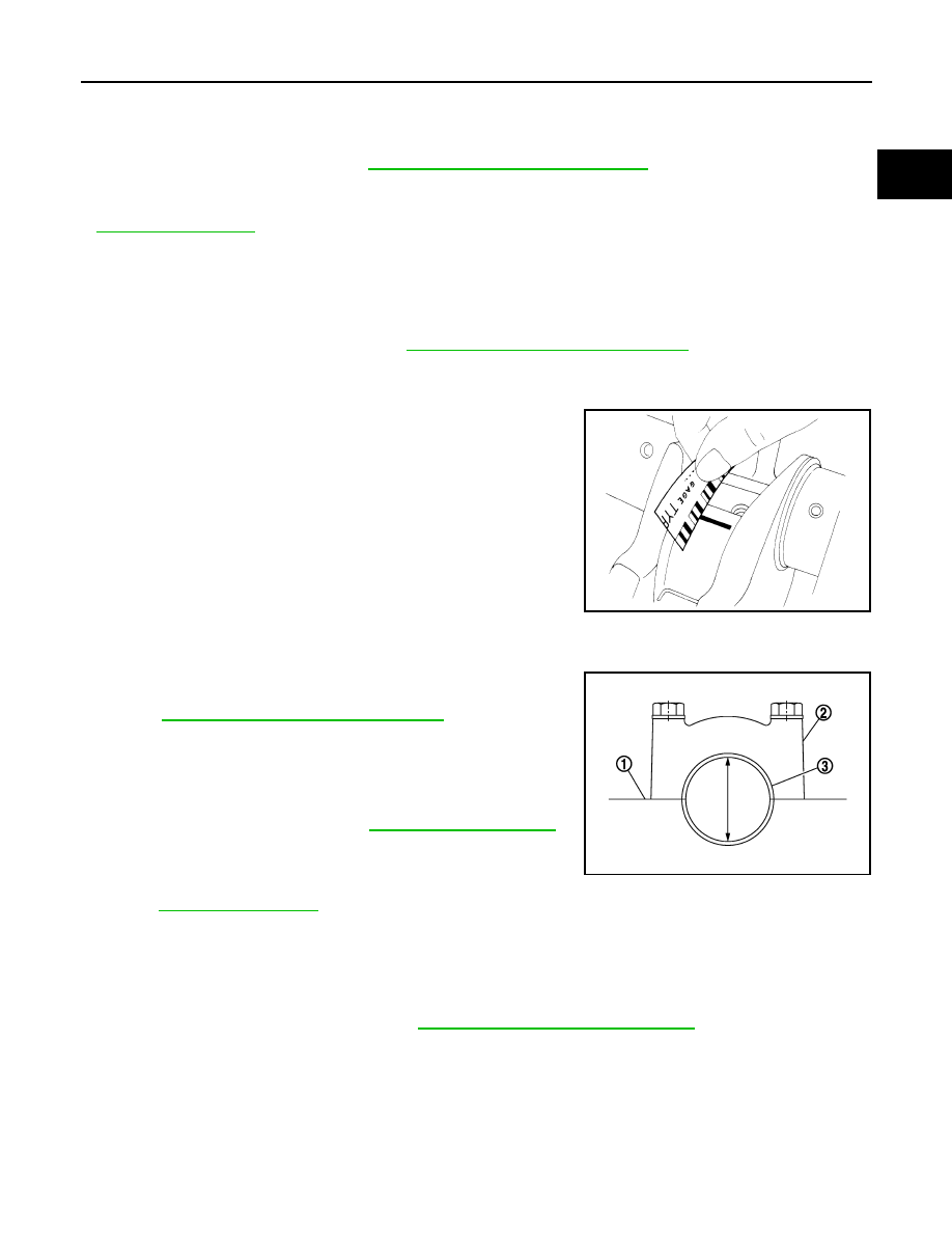
Measure the outer diameter of piston skirt with a micrometer (A).
Piston-to-Cylinder Bore Clearance
Calculate by piston skirt diameter and cylinder bore inner diameter [direction (B), position (D)].
(Clearance) = (Cylinder bore inner diameter) – (Piston skirt diameter).
• If the calculated value exceeds the limit, replace piston and piston pin assembly. Refer to
Re-boring Cylinder Bore
1.
Cylinder bore size is determined by adding piston to cylinder bore clearance to piston skirt diameter.
2.
Install main bearing cap, and tighten to the specified torque. Otherwise, cylinder bores may be distorted in
final assembly.
3.
Cut cylinder bores.
NOTE:
• When any cylinder needs boring, all other cylinders must also be bored.
• Do not cut too much out of cylinder bore at a time. Cut only 0.05 mm (0.0020 in) or so in diameter at a
time.
4.
Hone cylinders to obtain the specified piston to cylinder bore clearance.
5.
Measure finished cylinder bore for the out-of-round and taper.
NOTE:
Perform measurement after cylinder bore cools down.
CRANKSHAFT MAIN JOURNAL DIAMETER
• Measure the outer diameter of crankshaft main journals with a micrometer.
• If out of the standard, measure the main bearing oil clearance. Then use undersize bearing. Refer to
CRANKSHAFT PIN JOURNAL DIAMETER
Measure point
: Refer to
.
Standard
JPBIA0227ZZ
Standard and limit
: Refer to
.
Re-bored size calculation: D = A + B – C
where,
A: Piston skirt diameter as measured
B: Piston to cylinder bore clearance (standard value)
C: Honing allowance 0.02 mm (0.0008 in)
D: Bored diameter
Standard
: Refer to
.
EM-270
< UNIT DISASSEMBLY AND ASSEMBLY >
[VK50VE]
CYLINDER BLOCK
• Measure the outer diameter of crankshaft pin journal with a
micrometer (A).
• If out of the standard, measure the connecting rod bearing oil
clearance. Then use undersize bearing. Refer to
.
CRANKSHAFT OUT-OF-ROUND AND TAPER
• Measure the dimensions at four different points as shown in the
figure on each main journal and pin journal with a micrometer.
• Out-of-round is indicated by the difference in the dimensions
between (d) and (c) at (a) and (b).
• Taper is indicated by the difference in the dimensions between.
• If the measured value exceeds the limit, correct or replace crankshaft.
• If corrected, measure the bearing oil clearance of the corrected main journal and/or pin journal. Then select
the main bearing and/or connecting rod bearing. Refer to
.
CRANKSHAFT RUNOUT
• Place V-block on precise flat table, and support the journals on
both ends of crankshaft.
• Place a dial indicator straight up on the No. 3 journal.
• While rotating crankshaft, read the movement of the pointer on a
dial indicator. (Total indicator reading)
• If it exceeds the limit, replace crankshaft.
CONNECTING ROD BEARING OIL CLEARANCE
Method by Calculation
• Install connecting rod bearings (1) to connecting rod (2) and con-
necting rod cap, and tighten connecting rod bolts to the specified
torque. Refer to
EM-256, "Disassembly and Assembly"
for the
tightening procedure.
Standard
: Refer to
JPBIA0228ZZ
JPBIA0229ZZ
Out-of-round (Difference between “c” and “d”)
: Refer to
Taper (Difference between “a”and “b”)
Standard and limit
: Refer to
.
SEM346D
JPBIA0230ZZ
CYLINDER BLOCK
EM-271
< UNIT DISASSEMBLY AND ASSEMBLY >
[VK50VE]
C
D
E
F
G
H
I
J
K
L
M
A
EM
N
P
O
• Measure the inner diameter of connecting rod bearing with an inside micrometer.
(Oil clearance) = (Connecting rod bearing inner diameter) – (Crankshaft pin journal diameter)
• If the calculated value exceeds the limit, select proper connecting rod bearing according to connecting rod
big end diameter and crankshaft pin journal diameter to obtain the specified bearing oil clearance. Refer to
.
Method of Using Plastigage
• Remove oil and dust on crankshaft pin journal and the surfaces of each bearing completely.
• Cut a plastigage slightly shorter than the bearing width, and place it in crankshaft axial direction, avoiding oil
holes.
• Install connecting rod bearings to connecting rod and connecting rod bearing cap, and tighten connecting
rod bolts to the specified torque. Refer to
EM-256, "Disassembly and Assembly"
for the tightening proce-
dure.
CAUTION:
Never rotate crankshaft.
• Remove connecting rod bearing cap and bearings, and using the
scale on the plastigage bag, measure the plastigage width.
NOTE:
The procedure when the measured value exceeds the limit is the
same as that described in the “Method by Calculation”.
MAIN BEARING OIL CLEARANCE
Method by Calculation
• Install main bearings (3) to cylinder block (1) and main bearing cap
(2), and tighten main bearing cap bolts to the specified torque.
Refer to
EM-256, "Disassembly and Assembly"
for the tightening
procedure.
• Measure the inner diameter of main bearing with a bore gauge.
(Oil clearance) = (Main bearing inner diameter) – (Crankshaft main
journal diameter)
• If the calculated value exceeds the limit, select proper main bear-
ing according to main bearing inner diameter and crankshaft main
journal diameter to obtain the specified bearing oil clearance.
Refer to
Method of Using Plastigage
• Remove engine oil and dust on crankshaft journal and the surfaces of each bearing completely.
• Cut a plastigage slightly shorter than the bearing width, and place it in crankshaft axial direction, avoiding oil
holes.
• Install main bearing to cylinder block and main bearing cap, and tighten main bearing cap bolts with main
bearing cap to the specified torque. Refer to
EM-256, "Disassembly and Assembly"
dure.
CAUTION:
Never rotate crankshaft.
Standard and limit
: Refer to
EM-292, "Connecting Rod Bearing"
.
JPBIA0231ZZ
Standard and limit
: Refer to
.
JPBIA0232ZZ
Нет комментариевНе стесняйтесь поделиться с нами вашим ценным мнением.
Текст