Infiniti FX35, FX50 (S51). Manual — part 991
EM-264
< UNIT DISASSEMBLY AND ASSEMBLY >
[VK50VE]
CYLINDER BLOCK
• Be sure that front mark (H) on connecting rod bearing cap is facing the front of the engine.
16. Tighten connecting rod bolts as per the following:
a.
Inspect the outer diameter of connecting rod bolt. Refer to
.
b.
Apply engine oil to the threads and seats of connecting rod bolts.
c.
Tighten connecting rod bolts.
d.
Completely loosen connecting rod bolts.
e.
Tighten connecting rod bolts.
f.
Tighten connecting rod bolts. (clockwise)
CAUTION:
Always use the angle wrench [SST: KV10112100 (BT8653-A)]. Never make judgment by visual
inspection.
• After tightening connecting rod bolts, check that crankshaft rotates smoothly.
• Check the connecting rod side clearance. Refer to
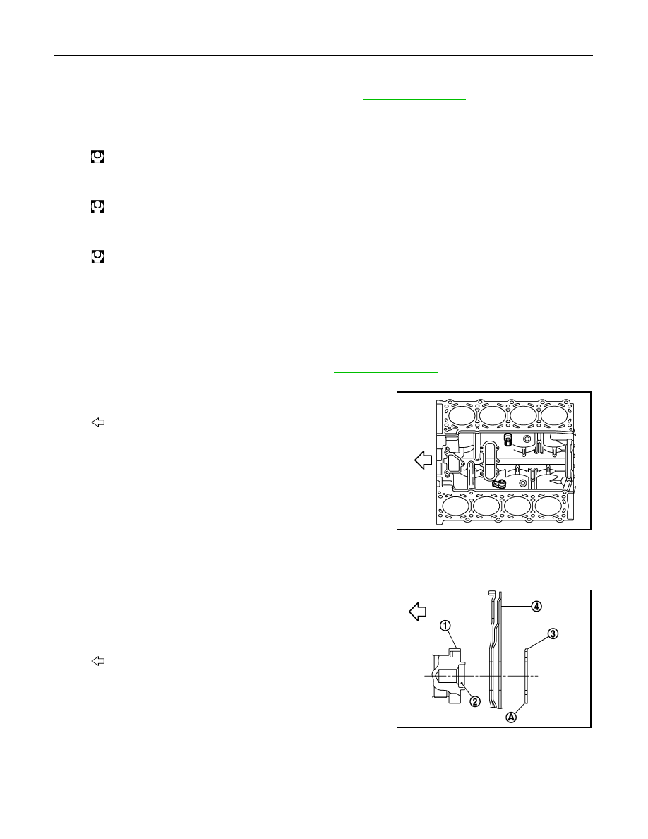
17. Install knock sensors.
• Install knock sensors in the direction shown in the figure.
• After installing knock sensor, connect harness connector, and
lay it out to front of the engine.
CAUTION:
• Never tighten mounting bolts while holding connector.
• If any impact by dropping is applied to knock sensor,
replace it with new one.
NOTE:
• Check that there is no foreign material on the cylinder block
mating surface and the back surface of knock sensor.
• Check that knock sensor does not interfere with other parts.
18. Install oil filter (for VVEL ladder assembly).
19. Install drive plate.
• Install drive plate (4) and reinforcement plate (3) as shown in
the figure.
• When installing drive plate to crankshaft (1), be sure to cor-
rectly align crankshaft side dowel pin and drive plate side
dowel pin hole.
CAUTION:
If these are not aligned correctly, engine runs roughly and
“MIL” illuminates.
• Holding ring gear with the ring gear stopper [SST: KV10119200 (J-49277)].
• Tighten the mounting bolts crosswise over several times.
20. Assemble in the reverse order of disassembly.
: 28.4 N·m (2.9 kg-m, 21 ft-lb)
: 0 N·m (0 kg-m, 0 ft-lb)
: 24.5 N·m (2.5 kg-m, 18 ft-lb)
Angle tightening: 90 degrees
: Engine front
2
: Pilot converter
A
: Rounded
: Engine front
JPBIA2274ZZ
JPBIA2275ZZ
CYLINDER BLOCK
EM-265
< UNIT DISASSEMBLY AND ASSEMBLY >
[VK50VE]
C
D
E
F
G
H
I
J
K
L
M
A
EM
N
P
O
Inspection
INFOID:0000000005245261
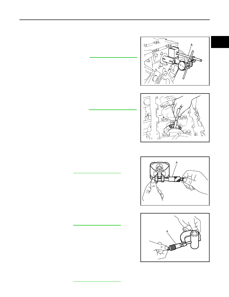
CRANKSHAFT END PLAY
• Measure the clearance between thrust bearings and crankshaft
arm when crankshaft is moved fully forward or backward with a dial
indicator (A).
• If the measured value exceeds the limit, replace thrust bearings,
and measure again. If it still exceeds the limit, replace crankshaft
also.
CONNECTING ROD SIDE CLEARANCE
• Measure the side clearance between connecting rod and crank-
shaft arm with a feeler gauge (A).
• If the measured value exceeds the limit, replace connecting rod,
and measure again. If it still exceeds the limit, replace crankshaft
also.
PISTON TO PISTON PIN OIL CLEARANCE
Piston Pin Hole Diameter
Measure the inner diameter of piston pin hole with an inside
micrometer (A).
Piston Pin Outer Diameter
Measure the outer diameter of piston pin with a micrometer (A).
Piston to Piston Pin Oil Clearance
(Piston to piston pin oil clearance) = (Piston pin hole diameter) – (Piston pin outer diameter)
Standard and limit
: Refer to
.
JPBIA2477ZZ
Standard and limit
: Refer to
JPBIA2476ZZ
Standard
: Refer to
JPBIA0217ZZ
Standard
: Refer to
JPBIA0218ZZ
Standard
: Refer to
EM-266
< UNIT DISASSEMBLY AND ASSEMBLY >
[VK50VE]
CYLINDER BLOCK
• If the calculated value is out of the standard, replace piston and piston pin assembly.
• When replacing piston and piston pin assembly, refer to
.
NOTE:
Piston is available together with piston pin as assembly.
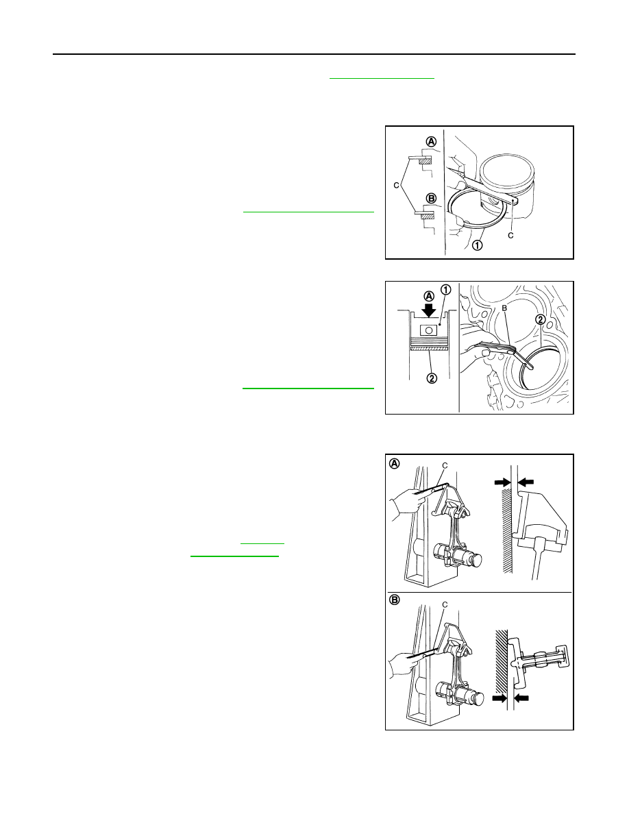
PISTON RING SIDE CLEARANCE
• Measure the side clearance of piston ring (1) and piston ring
groove with a feeler gauge (C).
• If the measured value exceeds the limit, replace piston ring, and
measure again. If it still exceeds the limit, replace piston also.
PISTON RING END GAP
• Check that the cylinder bore inner diameter is within the specifica-
tion.
• Lubricate with new engine oil to piston (1) and piston ring (2), and
then insert piston ring until middle of cylinder with piston, and mea-
sure the piston ring end gap with a feeler gauge (B).
• If the measured value exceeds the limit, replace piston ring, and
measure again. If it still exceeds the limit, re-bore cylinder and use
oversize piston and piston rings.
CONNECTING ROD BEND AND TORSION
• Check with a connecting rod aligner.
• If it exceeds the limit, replace connecting rod assembly.
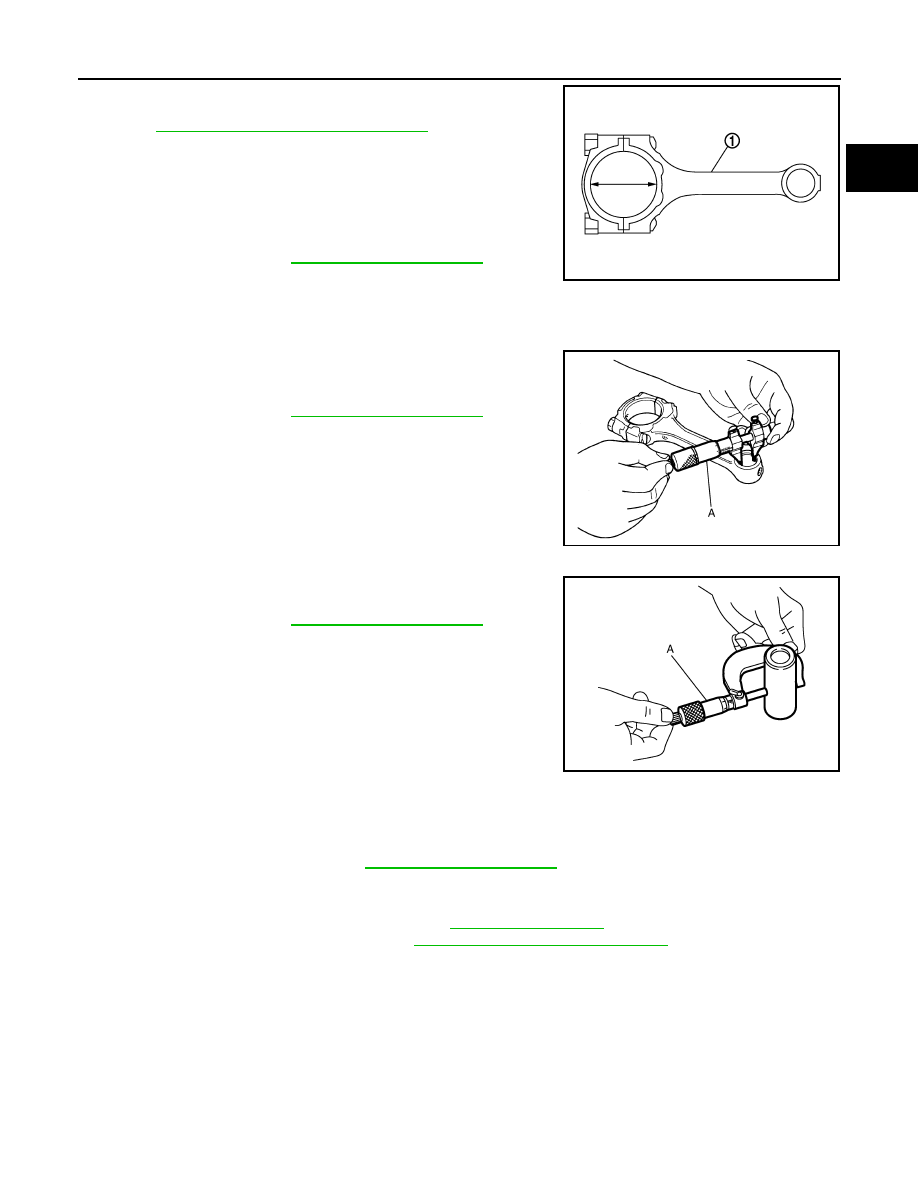
CONNECTING ROD BIG END DIAMETER
A
: OK
B
: NG
Standard and limit
: Refer to
.
JPBIA2276ZZ
A
: Press-fit
Standard and limit
: Refer to
JPBIA2277ZZ
A
: Bend
B
: Torsion
C
: Feeler gauge
Bend limit
: Refer to
Torsion limit
JPBIA0221ZZ
CYLINDER BLOCK
EM-267
< UNIT DISASSEMBLY AND ASSEMBLY >
[VK50VE]
C
D
E
F
G
H
I
J
K
L
M
A
EM
N
P
O
• Install connecting rod bearing cap without installing connecting rod
bearing, and tighten connecting rod bolts to the specified torque.
Refer to
EM-256, "Disassembly and Assembly"
for the tightening
procedure.
• Measure the inner diameter of connecting rod big end with an
inside micrometer.
• If out of the standard, replace connecting rod assembly.
CONNECTING ROD BUSHING OIL CLEARANCE
Connecting Rod Bushing Inner Diameter
Measure the inner diameter of connecting rod bushing with an inside
micrometer (A).
Piston Pin Outer Diameter
Measure the outer diameter of piston pin with a micrometer (A).
Connecting Rod Bushing Oil Clearance
(Connecting rod bushing oil clearance) = (Connecting rod bushing inner diameter) – (Piston pin outer diame-
ter)
• If the calculated value exceeds the limit, replace connecting rod assembly and/or piston and piston pin
assembly.
• If replacing piston and piston pin assembly, refer to
• If replacing connecting rod assembly, refer to
EM-275, "Connecting Rod Bearing"
to select the connecting
rod bearing.
CYLINDER BLOCK DISTORTION
• Using a scraper, remove gasket on the cylinder block surface, and also remove engine oil, scale, carbon, or
other contamination.
CAUTION:
Be careful not to allow gasket flakes to enter engine oil or engine coolant passages.
1
: Connecting rod
Standard
: Refer to
JPBIA0222ZZ
Standard
: Refer to
JPBIA0223ZZ
Standard
: Refer to
JPBIA0218ZZ
Standard and limit
: Refer to
Нет комментариевНе стесняйтесь поделиться с нами вашим ценным мнением.
Текст