Infiniti FX35, FX50 (S51). Manual — part 68
AV
FRONT DISPLAY UNIT
AV-45
< ECU DIAGNOSIS INFORMATION >
[WITHOUT NAVIGATION]
C
D
E
F
G
H
I
J
K
L
M
B
A
O
P
9
(B)
Ground
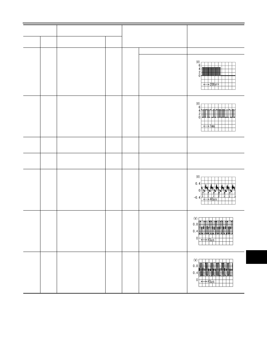
RGB area (YS) signal
Input
Ignition
switch
ON
At RGB image is displayed.
5.0 V
At AUX image is displayed.
11
(Y)
Ground
Communication signal
(CONT
→
DISP)
Input
Ignition
switch
ON
When adjusting display
brightness.
13
(BR)
Ground
Inverter ground
—
Ignition
switch
ON
—
0 V
14
(LG)
Ground
Signal ground
—
Ignition
switch
ON
—
0 V
15
(SB)
Ground
Composite image signal
Input
Ignition
switch
ON
At camera image is dis-
played.
17
(B)
Ground
RGB signal (R: red)
Input
Ignition
switch
ON
Start Confirmation/Adjust-
ment mode, and then dis-
play color bar by selecting
“Color Spectrum Bar” on
Display Diagnosis screen.
18
(R)
Ground
RGB signal (B: blue)
Input
Ignition
switch
ON
Start Confirmation/Adjust-
ment mode, and then dis-
play color bar by selecting
“Color Spectrum Bar” on
Display Diagnosis screen.
Terminal
(Wire color)
Description
Condition
Reference value
(Approx.)
+
–
Signal name
Input/
Output
PKIB4948J
PKIB5039J
SKIB2251J
JSNIA1029ZZ
JSNIA1031ZZ
AV-46
< ECU DIAGNOSIS INFORMATION >
[WITHOUT NAVIGATION]
FRONT DISPLAY UNIT
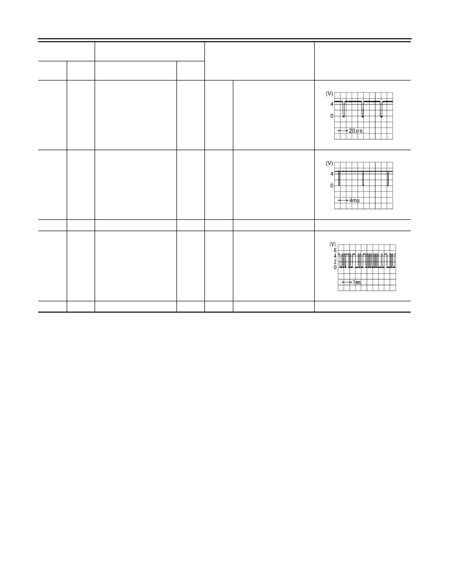
19
(G)
Ground
RGB synchronizing signal
Input
Ignition
switch
ON
—
20
(W)
Ground
Vertical synchronizing (VP)
signal
Output
Ignition
switch
ON
—
21
—
Shield
—
—
—
—
22
(BR)
Ground
Communication signal
(DISP
→
CONT)
Output
Ignition
switch
ON
When adjusting display
brightness.
23
—
Shield
—
—
—
—
Terminal
(Wire color)
Description
Condition
Reference value
(Approx.)
+
–
Signal name
Input/
Output
SKIB3603E
SKIB3598E
PKIB5039J
AV
BOSE AMP.
AV-47
< ECU DIAGNOSIS INFORMATION >
[WITHOUT NAVIGATION]
C
D
E
F
G
H
I
J
K
L
M
B
A
O
P
BOSE AMP.
Reference Value
INFOID:0000000005527824
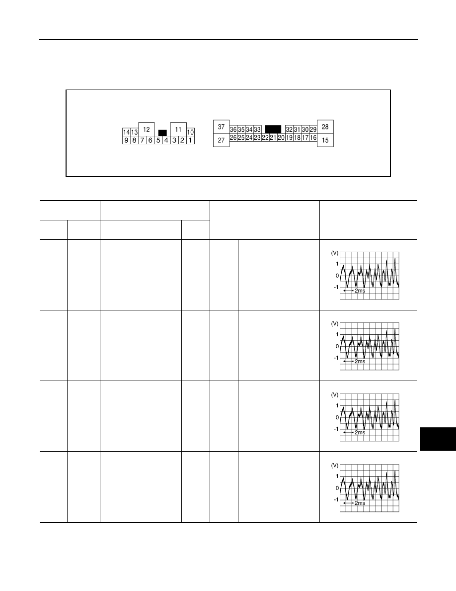
TERMINAL LAYOUT
PHYSICAL VALUES
JSNIA0760ZZ
Terminal
(Wire color)
Description
Condition
Reference value
(Approx.)
+
–
Signal name
Input/
Output
1
(Y)
10
(G)
Sound signal rear door
speaker LH
Output
Ignition
switch
ON
Sound output
2
(SB)
3
(V)
Sound signal rear door
speaker RH
Output
Ignition
switch
ON
Sound output
4
(L)
5
(P)
Sound signal front door
speaker LH
Output
Ignition
switch
ON
Sound output
6
(O)
7
(W)
Sound signal front squawk-
er LH
Output
Ignition
switch
ON
Sound output
SKIB3609E
SKIB3609E
SKIB3609E
SKIB3609E
AV-48
< ECU DIAGNOSIS INFORMATION >
[WITHOUT NAVIGATION]
BOSE AMP.
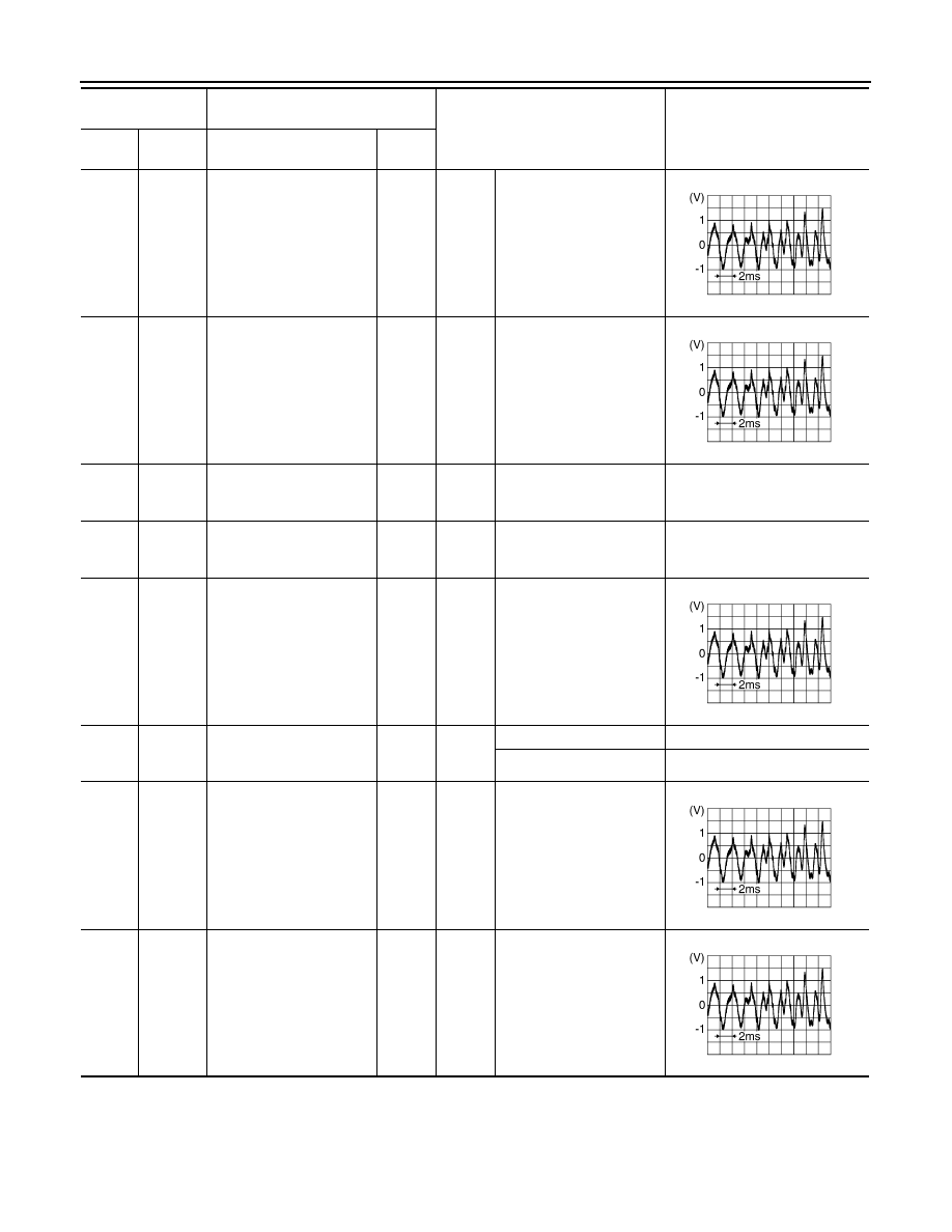
8
(LG)
13
(Y)
Sound signal front door
speaker RH
Output
Ignition
switch
ON
Sound output
9
(G)
14
(R)
Sound signal woofer and
rear squawker
Output
Ignition
switch
ON
Sound output
11
(GR)
Ground
Battery power supply
Input
Ignition
switch
ON
—
Battery voltage
12
(B)
Ground
Ground
—
Ignition
switch
ON
—
0 V
15
(Y)
28
(G)
Sound signal center speak-
er
Output
Ignition
switch
ON
Sound output
17
(O)
Ground
Mode change signal
Input
Ignition
switch
ON
Driver's Audio Stage ON
0 V
Driver's Audio Stage OFF
8.5 V
18
(P)
32
(L)
Sound signal front LH
Input
Ignition
switch
ON
Sound output
19
(R)
20
(G)
Sound signal front RH
Input
Ignition
switch
ON
Sound output
Terminal
(Wire color)
Description
Condition
Reference value
(Approx.)
+
–
Signal name
Input/
Output
SKIB3609E
SKIB3609E
SKIB3609E
SKIB3609E
SKIB3609E
Нет комментариевНе стесняйтесь поделиться с нами вашим ценным мнением.
Текст