Infiniti FX35, FX50 (S51). Manual — part 871
P1550 BATTERY CURRENT SENSOR
EC-1025
< DTC/CIRCUIT DIAGNOSIS >
[VK50VE]
C
D
E
F
G
H
I
J
K
L
M
A
EC
N
P
O
2.
Also check harness for short to ground and short to power.
Is the inspection result normal?
YES
>> GO TO 13.
NO
>> GO TO 12.
12.
DETECT MALFUNCTIONING PART
Check the following.
• Harness connectors F10, E10
• Harness for open or short between battery current sensor and ECM
>> Repair open circuit, short to ground or short to power in harness or connectors.
13.
CHECK BATTERY CURRENT SENSOR
EC-1025, "Component Inspection"
.
Is the inspection result normal?
YES
>> GO TO 14.
NO
>> Replace battery negative cable assembly.
14.
CHECK INTERMITTENT INCIDENT
GI-36, "Intermittent Incident"
.
>> INSPECTION END
Component Inspection
INFOID:0000000005237518
1.
CHECK BATTERY CURRENT SENSOR
1.
Turn ignition switch OFF.
2.
Reconnect harness connectors disconnected.
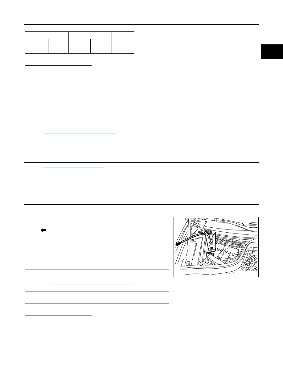
3.
Disconnect battery negative cable (1).
4.
Install jumper cable (A) between battery negative terminal and
body ground.
5.
Turn ignition switch ON.
6.
Check the voltage between ECM harness connector terminals
under the following conditions.
Before measuring the terminal voltage, confirm that the battery is fully charged. Refer to
.
Is the inspection result normal?
YES
>> INSPECTION END
NO
>> Replace battery negative cable assembly.
Battery current sensor
ECM
Continuity
Connector
Terminal
Connector
Terminal
E21
3
F111
76
Existed
: To body ground
ECM
Voltage (V)
Connector
+
–
Terminal
Terminal
F111
76
(Battery current sensor signal)
70
Approx. 2.5
JMBIA1512ZZ

EC-1026
< DTC/CIRCUIT DIAGNOSIS >
[VK50VE]
P1551, P1552 BATTERY CURRENT SENSOR
P1551, P1552 BATTERY CURRENT SENSOR
Description
INFOID:0000000005237519
The power generation voltage variable control enables fuel consumption to be decreased by reducing the
engine load which is caused by the power generation of the generator. The battery current sensor is installed
to the battery cable at the negative terminal. The sensor measures the charging/discharging current of the bat-
tery. Based on the sensor signal, ECM judges whether or not the power generation voltage variable control is
performed. When performing the power generation voltage variable control, ECM calculates the target power
generation voltage based on the sensor signal. And ECM sends the calculated value as the power generation
command value to IPDM E/R. For the details of the power generation voltage variable control, refer to
CAUTION:
Never connect the electrical component or the ground wire directly to the battery terminal. The con-
nection causes the malfunction of the power generation voltage variable control, and then battery dis-
charge may occur.
DTC Logic
INFOID:0000000005237520
DTC DETECTION LOGIC
DTC CONFIRMATION PROCEDURE
1.
PRECONDITIONING
If DTC Confirmation Procedure has been previously conducted, always perform the following procedure
before conducting the next test.
1.
Turn ignition switch OFF and wait at least 10 seconds.
2.
Turn ignition switch ON.
3.
Turn ignition switch OFF and wait at least 10 seconds.
TESTING CONDITION:
Before performing the following procedure, confirm that battery voltage is more than 8 V with ignition
switch ON
>> GO TO 2.
2.
PERFORM DTC CONFIRMATION PROCEDURE
1.
Turn ignition switch ON and wait at least 10 seconds.
2.
Check 1st trip DTC.
Is 1st trip DTC detected?
DTC No.
Trouble diagnosis name
DTC detecting condition
Possible cause
P1551
Battery current sensor circuit
low input
An excessively low voltage from
the sensor is sent to ECM.
• Harness or connectors
(Battery current sensor circuit is open or shorted.)
(Accelerator pedal position sensor 2 circuit is
shorted.)
[Camshaft position sensor (bank 1) circuit is
shorted.]
(Crankshaft position sensor circuit is shorted.)
(EVAP control system pressure sensor circuit is
shorted.)
[Exhaust valve timing control position sensor
(bank 1) circuit is shorted.]
(manifold absolute pressure sensor circuit is
shorted.)
• Battery current sensor
• Accelerator pedal position sensor
• Camshaft position sensor (bank 1)
• Crankshaft position sensor
• EVAP control system pressure sensor
• Exhaust valve timing control position sensor
(bank 1)
• manifold absolute pressure sensor
P1552
Battery current sensor circuit
high input
An excessively high voltage from
the sensor is sent to ECM.

P1551, P1552 BATTERY CURRENT SENSOR
EC-1027
< DTC/CIRCUIT DIAGNOSIS >
[VK50VE]
C
D
E
F
G
H
I
J
K
L
M
A
EC
N
P
O
YES
>> Go to
EC-1027, "Diagnosis Procedure"
NO
>> INSPECTION END
Diagnosis Procedure
INFOID:0000000005237521
1.
CHECK GROUND CONNECTION
1.
Turn ignition switch OFF.
2.
Check ground connection M95. Refer to Ground Inspection in
Is the inspection result normal?
YES
>> GO TO 2.
NO
>> Repair or replace ground connection.
2.
CHECK BATTERY CURRENT SENSOR POWER SUPPLY CIRCUIT-I
1.
Disconnect battery current sensor harness connector.
2.
Turn ignition switch ON.
3.
Check the voltage between battery current sensor harness connector and ground.
Is the inspection result normal?
YES
>> GO TO 9.
NO
>> GO TO 3.
3.
CHECK BATTERY CURRENT SENSOR POWER SUPPLY CIRCUIT-II
1.
Turn ignition switch OFF.
2.
Disconnect ECM harness connector.
3.
Check the continuity between battery current sensor harness connector and ECM harness connector.
Is the inspection result normal?
YES
>> GO TO 5.
NO
>> GO TO 4.
4.
DETECT MALFUNCTIONING PART
Check the following.
• Harness connectors F10, E10
• Harness for open between battery current sensor and ECM
>> Repair open circuit.
5.
CHECK SENSOR POWER SUPPLY CIRCUIT
Check harness for short to power and short to ground, between the following terminals.
Battery current sensor
Ground
Voltage (V)
Connector
Terminal
E21
1
Ground
Approx. 5
Battery current sensor
ECM
Continuity
Connector
Terminal
Connector
Terminal
E21
1
F111
95
Existed

EC-1028
< DTC/CIRCUIT DIAGNOSIS >
[VK50VE]
P1551, P1552 BATTERY CURRENT SENSOR
Is the inspection result normal?
YES
>> GO TO 6.
NO
>> Repair short to ground or short to power in harness or connectors.
6.
CHECK COMPONENTS
Check the following.
• Crankshaft position sensor (Refer to
EC-876, "Component Inspection"
• Camshaft position sensor (bank 1) (Refer to
EC-881, "Component Inspection"
• Exhaust valve timing control position sensor (bank 1) (Refer to
EC-978, "Component Inspection"
.)
• EVAP control system pressure sensor (Refer to
EC-917, "Component Inspection"
.)
• Manifold absolute pressure sensor (Refer to
EC-785, "Component Inspection"
Is the inspection result normal?
YES
>> GO TO 7.
NO
>> Replace malfunctioning component.
7.
CHECK APP SENSOR
EC-1081, "Component Inspection"
.
Is the inspection result normal?
YES
>> GO TO 14.
NO
>> GO TO 8.
8.
REPLACE ACCELERATOR PEDAL ASSEMBLY
1.
Replace accelerator pedal assembly.
2.
EC-1082, "Special Repair Requirement"
.
>> INSPECTION END
9.
CHECK BATTERY CURRENT SENSOR GROUND CIRCUIT FOR OPEN AND SHORT
1.
Turn ignition switch OFF.
2.
Disconnect ECM harness connector.
3.
Check the continuity between battery current sensor harness connector and ECM harness connector.
4.
Also check harness for short to ground and short to power.
Is the inspection result normal?
YES
>> GO TO 11.
NO
>> GO TO 10.
10.
DETECT MALFUNCTIONING PART
Check the following.
ECM
Sensor
Connector
Terminal
Name
Connector
Terminal
F111
87
Crankshaft position sensor
F2
1
91
Camshaft position sensor (bank 1)
F84
1
EVT control position sensor (bank 1)
F59
1
95
Battery current sensor
E21
1
EVAP control system pressure sensor
B252
3
manifold absolute pressure sensor
F65
1
M160
99
APP sensor (Without ICC)
E112
6
APP sensor (with ICC)
E116
3
Battery current sensor
ECM
Continuity
Connector
Terminal
Connector
Terminal
E21
2
F111
70
Existed
Нет комментариевНе стесняйтесь поделиться с нами вашим ценным мнением.
Текст