Infiniti FX35, FX50 (S51). Manual — part 1665

B2607 STEERING LOCK RELAY
SEC-73
< DTC/CIRCUIT DIAGNOSIS >
[INTELLIGENT KEY SYSTEM]
C
D
E
F
G
H
I
J
L
M
A
B
SEC
N
O
P
B2607 STEERING LOCK RELAY
Description
INFOID:0000000005249491
BCM requests to IPDM E/R to supply power to steering lock unit. After receiving the power, the steering lock
unit transmits an ON signal to BCM.
DTC Logic
INFOID:0000000005249492
DTC DETECTION LOGIC
NOTE:
• If DTC B2607 is displayed with DTC U1000, first perform the trouble diagnosis for DTC U1000. Refer to
• If DTC B2607 is displayed with DTC U1010, first perform the trouble diagnosis for DTC U1010. Refer to
DTC CONFIRMATION PROCEDURE
1.
PERFORM DTC CONFIRMATION PROCEDURE
1.
Press the push-button ignition switch under the following conditions.
-
Selector lever is in the P or N position.
-
Do not depress brake pedal.
2.
Steering lock is locked.
3.
Check “Self diagnostic result” with CONSULT-III.
Is DTC detected?
YES
>> Go to
NO
>> INSPECTION END
Diagnosis Procedure
INFOID:0000000005249493
1.
CHECK DTC WITH IPDM E/R
Check “Self diagnostic result” with CONSULT-III. Refer to
.
Is the inspection result normal?
YES
>> GO TO 2.
NO
>> Repair or replace the malfunctioning parts.
2.
CHECK STEERING LOCK UNIT POWER SUPPLY CIRCUIT
1.
Turn ignition switch OFF.
2.
Disconnect steering lock unit connector.
3.
Check voltage between steering lock unit harness connector and ground.
Is the inspection result normal?
YES
>> GO TO 4.
NO
>> GO TO 3.
DTC No.
Trouble diagnosis
name
DTC detecting condition
Possible cause
B2607
S/L RELAY
BCM detects that there is a difference between the
following statuses.
• Steering lock unit ON signal transmitted by IPDM
E/R
• The steering lock unit status feedback
• Harness or connectors (Steering
lock unit power supply circuit is
open or shorted)
• Steering lock relay (In IPDM E/R)
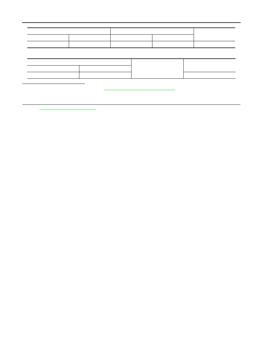
(+)
(–)
Condition
Voltage (V)
(Approx.)
Steering lock unit
Connector
Terminal
M40
1
Ground
Press push-button ignition switch when
steering lock is in lock condition.
Battery voltage

SEC-74
< DTC/CIRCUIT DIAGNOSIS >
[INTELLIGENT KEY SYSTEM]
B2607 STEERING LOCK RELAY
3.
CHECK STEERING LOCK UNIT CIRCUIT
1.
Turn ignition switch OFF.
2.
Disconnect IPDM E/R connector E5.
3.
Check continuity between steering lock unit harness connector and IPDM E/R harness connector.
4.
Check continuity between steering lock unit harness connector and ground.
Is the inspection result normal?
YES
>> Replace IPDM E/R. Refer to
PCS-34, "Removal and Installation"
NO
>> Repair or replace harness.
4.
CHECK INTERMITTENT INCIDENT
GI-36, "Intermittent Incident"
>> INSPECTION END
Steering lock unit
IPDM E/R
Continuity
Connector
Terminal
Connector
Terminal
M40
1
E5
11
Existed
Steering lock unit
Ground
Continuity
Connector
Terminal
M40
1
Not existed

B2608 STARTER RELAY
SEC-75
< DTC/CIRCUIT DIAGNOSIS >
[INTELLIGENT KEY SYSTEM]
C
D
E
F
G
H
I
J
L
M
A
B
SEC
N
O
P
B2608 STARTER RELAY
Description
INFOID:0000000005249494
Located in IPDM E/R, The sterter relay runs the starter motor. The starter relay is turned ON by the BCM when
the ignition switch is in the START position. IPDM E/R transmits the starter relay ON signal to BCM via CAN
communication.
DTC Logic
INFOID:0000000005249495
DTC DETECTION LOGIC
NOTE:
• If DTC B2608 is displayed with DTC U1000, first perform the trouble diagnosis for DTC U1000. Refer to
• If DTC B2608 is displayed with DTC U1010, first perform the trouble diagnosis for DTC U1010. Refer to
• If DTC B2608 is displayed with DTC B210D for IPDM E/R, first perform the trouble diagnosis for DTC
B210D. Refer to
DTC CONFIRMATION PROCEDURE
1.
PERFORM DTC CONFIRMATION PROCEDURE
1.
Press the push-button ignition switch under the following conditions.
-
Selector lever is in the P or N position.
-
Do not depress brake pedal.
2.
Check “Self diagnostic result” with CONSULT-III.
Is DTC detected?
YES
>> Go to
NO
>> INSPECTION END
Diagnosis Procedure
INFOID:0000000005249496
1.
CHECK BCM POWER SUPPLY CIRCUIT
1.
Turn ignition switch ON.
2.
Check voltage between BCM harness connector and ground.
Is the measurement value within the specification?
YES
>> GO TO 3.
NO
>> GO TO 2.
2.
CHECK STARTER RELAY CIRCUIT
1.
Turn ignition switch OFF.
2.
Disconnect BCM connector M121 and IPDM E/R connector E6.
3.
Check continuity between IPDM E/R harness connector and BCM harness connector.
DTC No.
Trouble diagnosis
name
DTC detecting condition
Possible cause
B2608
STARTER RELAY
BCM receives starter relay ON signal (CAN) from
IPDM E/R even if BCM turns the starter relay OFF.
• Harness or connectors
(Starter relay circuit is open or
shorted.)
• IPDM E/R
(+)
(–)
Condition
Voltage (V)
(Approx.)
BCM
Connector
Terminal
M121
52
Ground
Selector lever
N or P position
Battery voltage
Other than above
0
SEC-76
< DTC/CIRCUIT DIAGNOSIS >
[INTELLIGENT KEY SYSTEM]
B2608 STARTER RELAY
4.
Check continuity between IPDM E/R harness connector and ground.
Is the inspection result normal?
YES
>> Replace IPDM E/R. Refer to
PCS-34, "Removal and Installation"
NO
>> Repair or replace harness.
3.
CHECK INTERMITTENT INCIDENT
GI-36, "Intermittent Incident"
>> INSPECTION END
IPDM E/R
BCM
Continuity
Connector
Terminal
Connector
Terminal
E6
46
M121
52
Existed
IPDM E/R
Ground
Continuity
Connector
Terminal
E6
46
Not existed
Нет комментариевНе стесняйтесь поделиться с нами вашим ценным мнением.
Текст