Infiniti FX35, FX50 (S51). Manual — part 392
CCS-388
< SYSTEM DESCRIPTION >
[FCW]
FORWARD COLLISION WARNING SYSTEM
NOTE:
FCW ON indicator blinks when “C1B03” is detected.
FCW INITIAL STATE CHANGE
CAUTION:
Never change FCW initial state “ON”
⇒
“OFF” without the consent of the customer.
FCW initial state can be changed.
• FCW initial ON* - FCW function is automatically turned ON, when the ignition switch OFF
⇒
ON.
• FCW initial OFF - FCW function is still OFF when the ignition switch OFF
⇒
ON.
*: Factory setting
How to change FCW initial state
1.
Turn ignition switch ON.
2.
Switch FCW and LDP functions to OFF.
3.
Push and hold FCW switch for more than 4 seconds.
4.
Buzzer sounds and blinking of the lane departure warning lamp informs that the FCW initial state change
is completed.
FCW OPERATING CONDITION
• FCW ON indicator: ON
• Vehicle speed: Approximately 15 km/h (10 MPH) and above.
ICC sensor integrated unit input/output signal item
Input Signal Item
Output Signal Item
Vehicle condition
Indication on the combination meter
• When the FCW system malfunctions
• When the sensor window is dirty
• When driving into a strong light (i.e. sunlight)
NOTE:
Check that the IBA system is not OFF. The indicator lamp is shared
with IBA system.
JPOIA0179ZZ
Transmission Unit
Signal Name
Description
ABS actuator and elec-
tric unit (control unit)
Vehicle speed signal
Receives the vehicle speed signal (wheel speed) from ABS actuator and
electric unit (control unit) via CAN communication
Lame camera unit
[through ABS actuator
and electric unit (con-
trol unit)]
FCW switch signal
Receives the FCW switch signal from lame camera unit [through ABS ac-
tuator and electric unit (control unit)] via CAN communication.
Reception unit
Signal name
Description
Combination
meter (through
unified meter
and A/C amp.)
Meter display
signal
Vehicle ahead detection
indicator signal
Transmits the meter display signal to the combination meter
(through unified meter and A/C amp.) via CAN communication.
IBA OFF indicator lamp signal
Transmits the IBA OFF indicator signal to the combination meter
(through unified meter and A/C amp.) via CAN communication.
ICC warning
chime
Buzzer output signal
• Transmits the buzzer output signal to the brake booster control
unit via ITS communication.
• The brake booster control unit outputs the buzzer output signal
and operates the ICC warning chime.
Lane camera
unit
FCW ON indicator signal
Transmits the FCW ON indicator signal to the lane camera unit via
CAN communication.
CCS
FORWARD COLLISION WARNING SYSTEM
CCS-389
< SYSTEM DESCRIPTION >
[FCW]
C
D
E
F
G
H
I
J
K
L
M
B
N
P
A
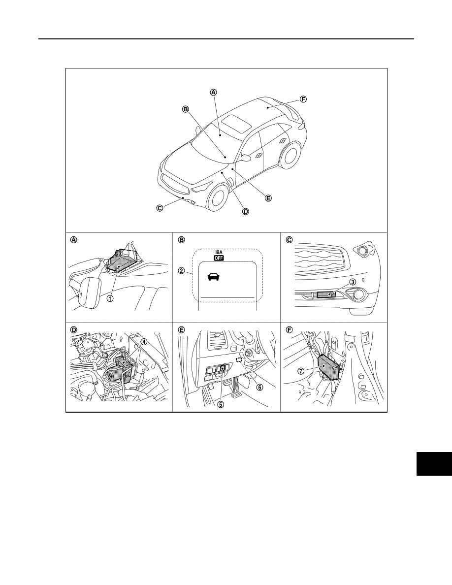
Component Parts Location
INFOID:0000000005502031
Component Description
INFOID:0000000005502032
1.
Lane camera unit
2.
Information display, IBA OFF indica-
tor lamp
3.
ICC sensor integrated unit
4.
ABS actuator and electric unit (con-
trol unit)
5.
FCW switch
6.
ICC warning chime
7.
Brake booster control unit
A.
Front of the map lamp
B.
On the combination meter
C.
Front bumper (LH)
D.
Inside the brake master cylinder cov-
er
E.
Instrument driver lower panel (LH)
F.
Luggage room (RH)
JPOIA0196ZZ

CCS-390
< SYSTEM DESCRIPTION >
[FCW]
FORWARD COLLISION WARNING SYSTEM
Component
Description
Lane camera unit
• Transmits FCW switch signal to ABS actuator and electric unit (control unit) unit via CAN com-
munication.
• Controls the FCW ON indicator when receiving an FCW ON indicator signal from the ICC sensor
integrated unit via CAN communication.
ABS actuator and electric unit
(control unit)
• Transmits vehicle speed signal to ICC sensor integrated unit via CAN communication.
• Transmits FCW switch signal to ICC sensor integrated unit via CAN communication.
FCW switch
Inputs the switch signal to lane camera unit.
FCW ON indicator
(On the FCW switch)
Indicates FCW system status.
Brake booster control unit
• The ICC sensor integrated unit transmits the buzzer output signal to the brake booster control
unit via ITS communication.
• The brake booster control unit outputs the buzzer output signal to the ICC warning chime.
Unified meter and A/C amp.
Receives the meter display signal, and IBA OFF indicator lamp signal from ICC sensor integrated
unit via CAN communication and transmits them to the combination meter via the communication
line.
Combination meter
Perform the following operations using the signals received from the unified meter and A/C amp.
via the communication line.
• Displays the FCW operation status using the meter display signal.
• Illuminates the IBA OFF indicator lamp using the IBA OFF indicator lamp signal.
ICC warning chime
Warning chime sounds when the vehicle distance from the vehicle ahead is too close
CCS
DIAGNOSIS SYSTEM (ICC SENSOR INTEGRATED UNIT)
CCS-391
< SYSTEM DESCRIPTION >
[FCW]
C
D
E
F
G
H
I
J
K
L
M
B
N
P
A
DIAGNOSIS SYSTEM (ICC SENSOR INTEGRATED UNIT)
Diagnosis Description
INFOID:0000000005502033
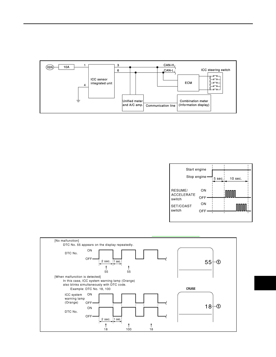
The DTC is displayed on the information display by operating the ICC steering switch.
ON BOARD SELF-DIAGNOSIS SYSTEM DIAGRAM
ON BOARD SELF-DIAGNOSIS OPERATION PROCEDURE
CAUTION:
Start condition of on board self-diagnosis
• ICC system OFF
• DCA system OFF
• Vehicle speed 0 km/h (0 MPH)
1.
Turn the ignition switch OFF.
2.
Start the engine.
3.
Wait for 5 seconds after starting the engine. Push up the
RESUME/ACCELERATE switch 5 times and push down the
SET/COAST switch 5 times within 10 seconds.
NOTE:
If the above operation cannot be performed within 10 seconds
after waiting for 5 seconds after starting the engine, repeat the
procedure from step 1.
4.
The DTC is displayed on the set vehicle speed indicator (1) on the ICC system display on the information
display when the on board self-diagnosis starts. Refer to
.
NOTE:
• It displays for up to 5 minutes and then stops.
JPOIA0189GB
PKIB8371E
JSOIA0008GB
Нет комментариевНе стесняйтесь поделиться с нами вашим ценным мнением.
Текст