Infiniti FX35, FX50 (S51). Manual — part 893
ICC BRAKE SWITCH
EC-1113
< DTC/CIRCUIT DIAGNOSIS >
[VK50VE]
C
D
E
F
G
H
I
J
K
L
M
A
EC
N
P
O
3.
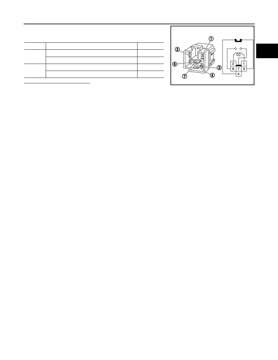
Check the continuity between ICC brake hold relay terminals
under the following conditions.
Is the inspection result normal?
YES
>> INSPECTION END
NO
>> Replace ICC brake hold relay
Terminals
Condition
Continuity
3 and 4
12 V direct current supply between terminals 1 and 2
Not existed
No current supply
Existed
6 and 7
12 V direct current supply between terminals 1 and 2
Existed
No current supply
Not existed
MBIB0063E
EC-1114
< DTC/CIRCUIT DIAGNOSIS >
[VK50VE]
IGNITION SIGNAL
IGNITION SIGNAL
Description
INFOID:0000000005237620
The ignition signal from the ECM is sent to and amplified by the power transistor. The power transistor turns
ON and OFF the ignition coil primary circuit. This ON/OFF operation induces the proper high voltage in the coil
secondary circuit.
Component Function Check
INFOID:0000000005237621
1.
INSPECTION START
Turn ignition switch OFF, and restart engine.
Does the engine start?
YES-1 >> With CONSULT-III: GO TO 2.
YES-2 >> Without CONSULT-III: GO TO 3.
NO
>> Go to
EC-1114, "Diagnosis Procedure"
.
2.
CHECK IGNITION SIGNAL FUNCTION
With CONSULT-III
1.
Perform “POWER BALANCE” in “ACTIVE TEST” mode with CONSULT-III.
2.
Check that each circuit produces a momentary engine speed drop.
Is the inspection result normal?
YES
>> INSPECTION END
NO
>> Go to
EC-1114, "Diagnosis Procedure"
.
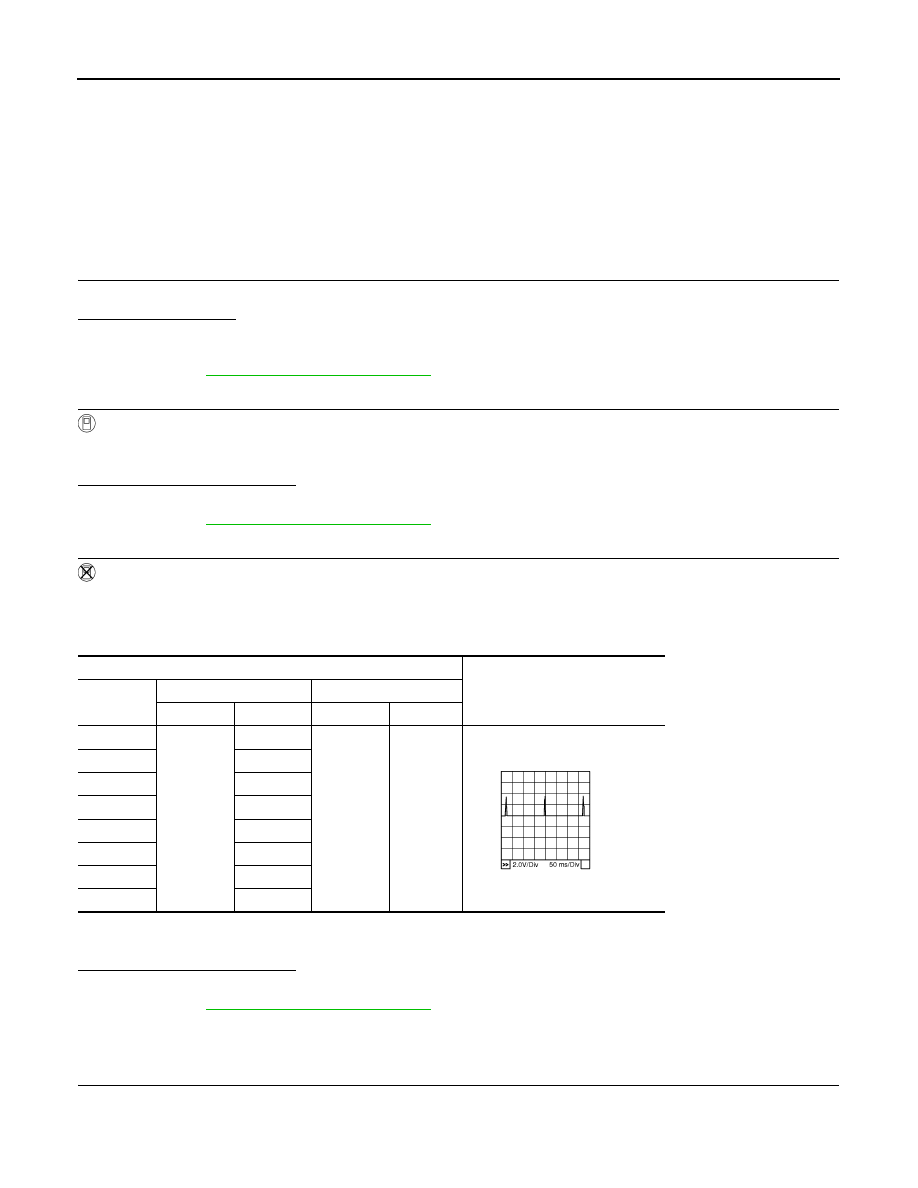
3.
CHECK IGNITION SIGNAL FUNCTION
Without CONSULT-III
1.
Let engine idle.
2.
Read the voltage signal between ECM harness connector terminals under the following conditions with an
oscilloscope.
NOTE:
The pulse cycle changes depending on rpm at idle.
Is the inspection result normal?
YES
>> INSPECTION END
NO
>> Go to
EC-1114, "Diagnosis Procedure"
.
Diagnosis Procedure
INFOID:0000000005237622
1.
CHECK IGNITION COIL POWER SUPPLY CIRCUIT-I
1.
Turn ignition switch OFF, wait at least 10 seconds and then turn it ON.
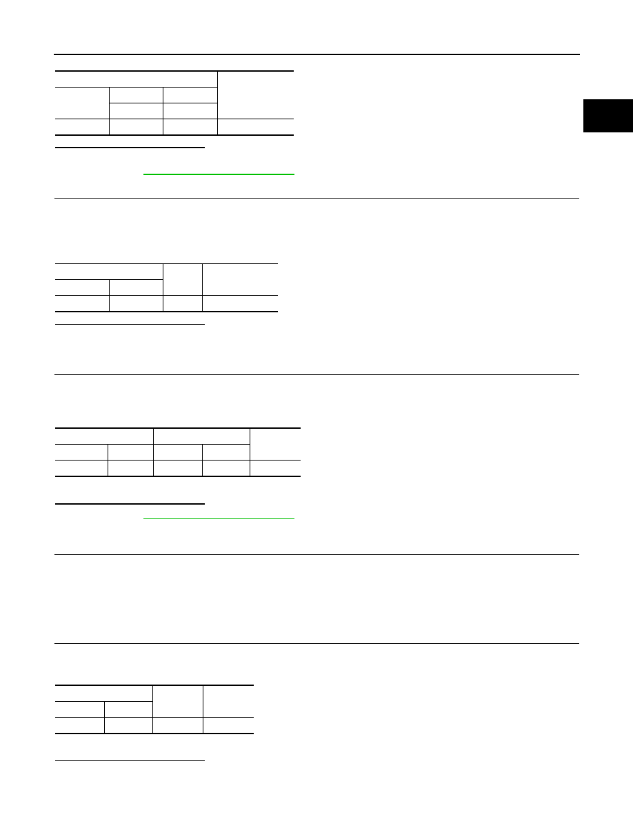
2.
Check the voltage between ECM harness connector terminals under the following conditions.
ECM
Voltage signal
Cylinder
+
–
Connector
Terminal
Connector
Terminal
1
F110
10
M160
128
2
9
3
13
4
14
5
18
6
22
7
26
8
30
PBIB0044E
IGNITION SIGNAL
EC-1115
< DTC/CIRCUIT DIAGNOSIS >
[VK50VE]
C
D
E
F
G
H
I
J
K
L
M
A
EC
N
P
O
Is the inspection result normal?
YES
>> GO TO 2.
NO
>> Go to
2.
CHECK IGNITION COIL POWER SUPPLY CIRCUIT-II
1.
Turn ignition switch OFF.
2.
Disconnect condenser harness connector.
3.
Turn ignition switch ON.
4.
Check the voltage between condenser harness connector and ground.
Is the inspection result normal?
YES
>> GO TO 5.
NO
>> GO TO 3.
3.
CHECK IGNITION COIL POWER SUPPLY CIRCUIT-III
1.
Turn ignition switch OFF.
2.
Disconnect IPDM E/R harness connector E7.
3.
Check the continuity between IPDM E/R harness connector and condenser harness connector.
4.
Also check harness for short to ground and short to power.
Is the inspection result normal?
YES
>> Go to
NO
>> GO TO 4.
4.
DETECT MALFUNCTIONING PART
Check the following.
• Harness connectors E10, F10
• Harness for open or short between IPDM E/R and condenser
>> Repair open circuit, short to ground or short to power in harness or connectors.
5.
CHECK CONDENSER GROUND CIRCUIT FOR OPEN AND SHORT
1.
Turn ignition switch OFF.
2.
Check the continuity between condenser harness connector and ground.
3.
Also check harness for short to power.
Is the inspection result normal?
YES
>> GO TO 6.
NO
>> Repair open circuit or short to power in harness or connectors.
ECM
Voltage
Connector
+
–
Terminal
Terminal
M160
121
128
Battery voltage
Condenser
Ground
Voltage
Connector
Terminal
F8
1
Ground
Battery voltage
IPDM E/R
Condenser
Continuity
Connector
Terminal
Connector
Terminal
E7
49
F8
1
Existed
Condenser
Ground
Continuity
Connector
Terminal
F8
2
Ground
Existed
EC-1116
< DTC/CIRCUIT DIAGNOSIS >
[VK50VE]
IGNITION SIGNAL
6.
CHECK CONDENSER
EC-1118, "Component Inspection (Condenser)"
Is the inspection result normal?
YES
>> GO TO 7.
NO
>> Replace condenser.
7.
CHECK IGNITION COIL POWER SUPPLY CIRCUIT-IV
1.
Reconnect all harness connectors disconnected.
2.
Disconnect ignition coil harness connector.
3.
Turn ignition switch ON.
4.
Check the voltage between ignition coil harness connector and ground.
Is the inspection result normal?
YES
>> GO TO 9.
NO
>> GO TO 8.
8.
DETECT MALFUNCTIONING PART
Check the following.
• Harness connector F10
• Harness for open or short between ignition coil and harness connector F10
>> Repair or replace harness or connectors.
9.
CHECK IGNITION COIL GROUND CIRCUIT FOR OPEN AND SHORT
1.
Turn ignition switch OFF.
2.
Check the continuity between ignition coil harness connector and ground.
3.
Also check harness for short to power.
Is the inspection result normal?
YES
>> GO TO 10.
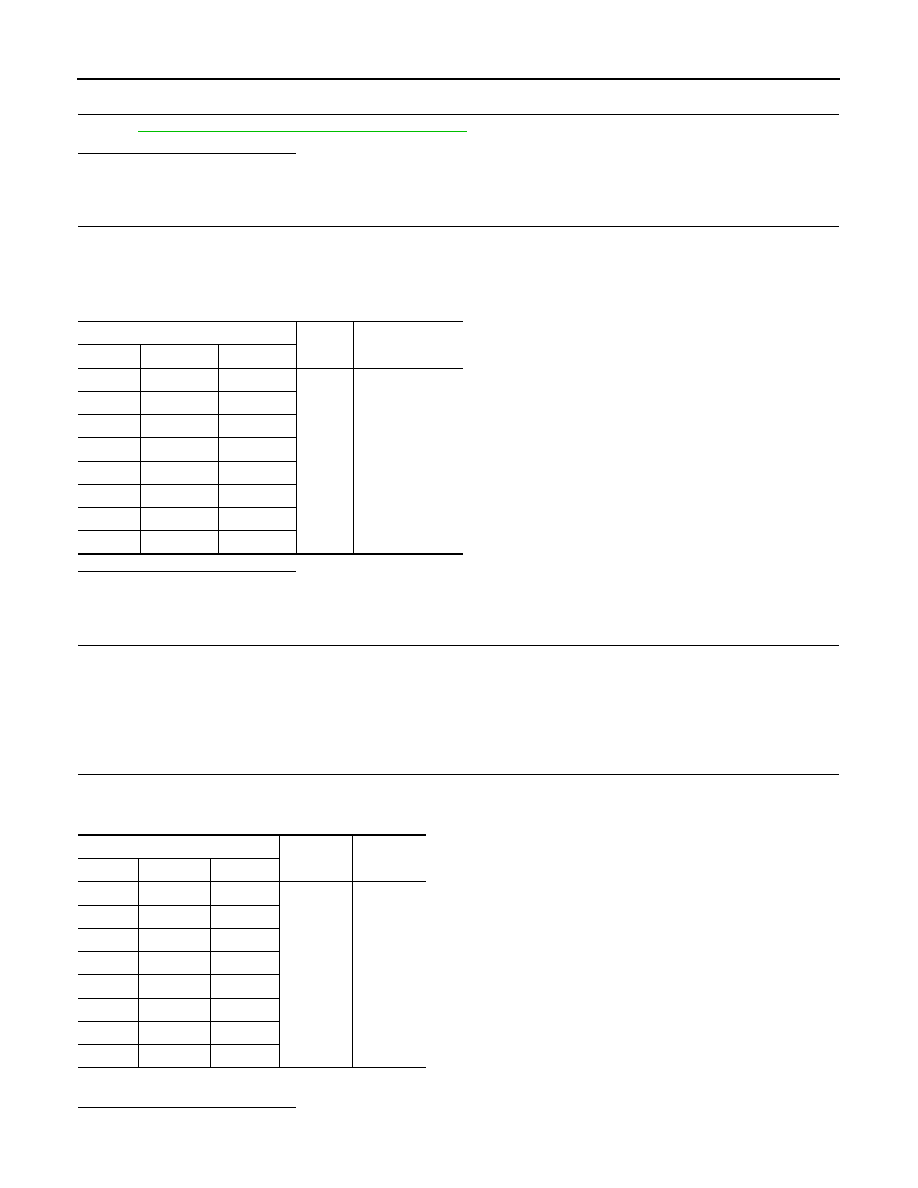
Ignition coil
Ground
Voltage
Cylinder
Connector
Terminal
1
F75
3
Ground
Battery voltage
2
F76
3
3
F77
3
4
F78
3
5
F79
3
6
F80
3
7
F81
3
8
F82
3
Ignition coil
Ground
Continuity
Cylinder
Connector
Terminal
1
F75
2
Ground
Existed
2
F76
2
3
F77
2
4
F78
2
5
F79
2
6
F80
2
7
F81
2
8
F82
2
Нет комментариевНе стесняйтесь поделиться с нами вашим ценным мнением.
Текст