Infiniti FX35, FX50 (S51). Manual — part 891
FUEL INJECTOR
EC-1105
< DTC/CIRCUIT DIAGNOSIS >
[VK50VE]
C
D
E
F
G
H
I
J
K
L
M
A
EC
N
P
O
5.
CHECK FUEL INJECTOR
EC-1105, "Component Inspection"
.
Is the inspection result normal?
YES
>> GO TO 6.
NO
>> Replace malfunctioning fuel injector.
6.
CHECK INTERMITTENT INCIDENT
GI-36, "Intermittent Incident"
.
Is the inspection result normal?
YES
>> Replace IPDM E/R.
NO
>> Repair open circuit, short to ground or short to power in harness or connectors.
Component Inspection
INFOID:0000000005237610
1.
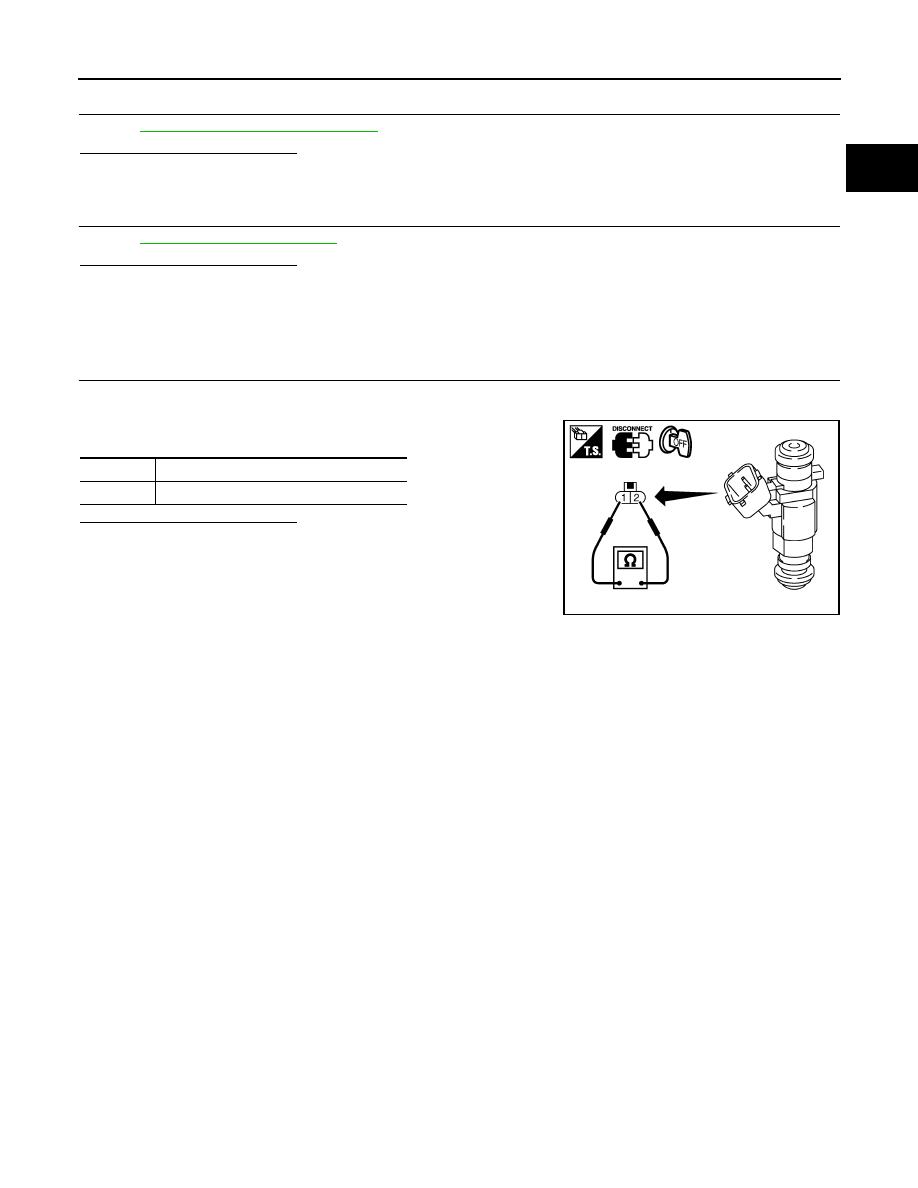
CHECK FUEL INJECTOR
1.
Turn ignition switch OFF.
2.
Disconnect fuel injector harness connector.
3.
Check resistance between fuel injector terminals as follows.
Is the inspection result normal?
YES
>> INSPECTION END
NO
>> Replace malfunctioning fuel injector.
Terminals
Resistance
1 and 2
11.1 - 14.3
Ω
[at 10 - 60
°
C (50 - 140
°
F)]
PBIB1727E
EC-1106
< DTC/CIRCUIT DIAGNOSIS >
[VK50VE]
FUEL PUMP
FUEL PUMP
Description
INFOID:0000000005237611
The ECM activates the fuel pump for 1 second after the ignition switch is turned ON to improve engine start-
ability. If the ECM receives a engine speed signal from the camshaft position sensor, it knows that the engine
is rotating, and causes the pump to operate. If the engine speed signal is not received when the ignition switch
is ON, the engine stalls. The ECM stops pump operation and prevents battery discharging, thereby improving
safety. The ECM does not directly drive the fuel pump. It sends the control signal to the fuel pump control mod-
ule, which in turn controls the fuel pump. Refer to
.
Component Function Check
INFOID:0000000005237612
1.
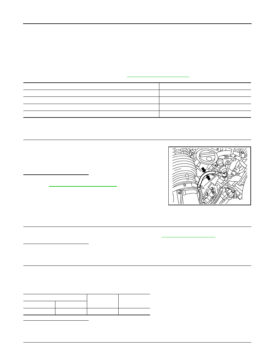
CHECK FUEL PUMP FUNCTION
1.
Turn ignition switch ON.
2.
Pinch fuel feed hose (1) with two fingers.
Is the inspection result normal?
YES
>> INSPECTION END
NO
>>
EC-1106, "Diagnosis Procedure"
Diagnosis Procedure
INFOID:0000000005237613
1.
CHECK GROUND CONNECTION
1.
Turn ignition switch OFF.
2.
Check ground connection M95. Refer to Ground Inspection in
Is the inspection result normal?
YES
>> GO TO 2.
NO
>> Repair or replace ground connection.
2.
CHECK FPCM POWER SUPPLY CIRCUIT
1.
Turn ignition switch OFF.
2.
Disconnect FPCM harness connector.
3.
Turn ignition switch ON.
4.
Check the voltage between FPCM harness connector and ground.
Is the inspection result normal?
YES
>> GO TO 4.
NO
>> GO TO 3.
3.
DETECT MALFUNCTIONING PART
Condition
Fuel pump operation
Ignition switch is turned to ON.
Operates for 1 second.
Engine running and cranking
Operates.
When engine is stopped
Stops in 1.5 seconds.
Except as shown above
Stops.
Fuel pressure pulsation should be felt on the fuel feed
hose for 1 second after ignition switch is turned ON.
JMBIA1562ZZ
FPCM
Ground
Voltage
Connector
Terminal
B31
10
Ground
Battery voltage

FUEL PUMP
EC-1107
< DTC/CIRCUIT DIAGNOSIS >
[VK50VE]
C
D
E
F
G
H
I
J
K
L
M
A
EC
N
P
O
Check the following.
• Harness connectors B3, E121
• 15 A fuse (No.41)
• Harness for open or short between FPCM and IPDM E/R
>> Repair open circuit, short to ground or short to power in harness or connectors.
4.
CHECK FPCM GROUND CIRCUIT FOR OPEN AND SHORT
1.
Turn ignition switch OFF.
2.
Check the continuity between FPCM harness connector and ground.
3.
Also check harness for short to power.
Is the inspection result normal?
YES
>> GO TO 5.
NO
>> Repair open circuit or short to power in harness or connectors.
5.
CHECK FPCM INPUT AND OUTPUT CIRCUITS FOR OPEN AND SHORT
1.
Disconnect ECM harness connector.
2.
Check the continuity between FPCM harness connector and ECM harness connector.
3.
Also check harness for short to ground and short to power.
Is the inspection result normal?
YES
>> GO TO 7.
NO
>> GO TO 6.
6.
DETECT MALFUNCTIONING PART
Check the following.
• Harness connectors B1, M7
• Harness for open or short between FPCM and ECM
>> Repair open circuit, short to ground or short to power in harness or connectors.
7.
CHECK FUEL PUMP CONTROL CIRCUIT FOR OPEN AND SHORT
1.
Disconnect “fuel level sensor unit and fuel pump (main)” harness connector.
2.
Check the continuity between FPCM harness connector and “fuel level sensor unit and fuel pump (main)”
harness connector.
3.
Also check harness for short to ground and short to power.
Is the inspection result normal?
YES
>> GO TO 8.
NO
>> Repair open circuit, short to ground or short to power in harness or connectors.
FPCM
Ground
Continuity
Connector
Terminal
B31
5
Ground
Existed
FPCM
ECM
Continuity
Connector
Terminal
Connector
Terminal
B31
8
M160
125
Existed
9
112
FPCM
Fuel level sensor unit and fuel pump (main)
Continuity
Connector
Terminal
Connector
Terminal
B31
6
B22
3
Existed
7
1

EC-1108
< DTC/CIRCUIT DIAGNOSIS >
[VK50VE]
FUEL PUMP
8.
CHECK FUEL PUMP
EC-1108, "Component Inspection"
.
Is the inspection result normal?
YES
>> GO TO 9.
NO
>> Replace fuel pump.
9.
CHECK FPCM
EC-1001, "Component Inspection"
.
Is the inspection result normal?
YES
>> GO TO 10.
NO
>> Replace FPCM.
10.
CHECK INTERMITTENT INCIDENT
GI-36, "Intermittent Incident"
>> INSPECTION END
Component Inspection
INFOID:0000000005237614
1.
CHECK FUEL PUMP
1.
Turn ignition switch OFF.
2.
Disconnect “fuel level sensor unit and fuel pump (main)” harness connector.
3.
Check resistance between “fuel level sensor unit and fuel pump (main)” terminals as follows.
Is the inspection result normal?
YES
>> INSPECTION END
NO
>> Replace “fuel level sensor unit and fuel pump (main)”
Terminals
Resistance
1 and 3
0.2 - 5.0
Ω
[at 25
°
C (77
°
F)]
Нет комментариевНе стесняйтесь поделиться с нами вашим ценным мнением.
Текст