Infiniti EX35. Manual — part 1386
STEERING GEAR AND LINKAGE
ST-25
< ON-VEHICLE REPAIR >
C
D
E
F
H
I
J
K
L
M
A
B
ST
N
O
P
STEERING GEAR AND LINKAGE
2WD
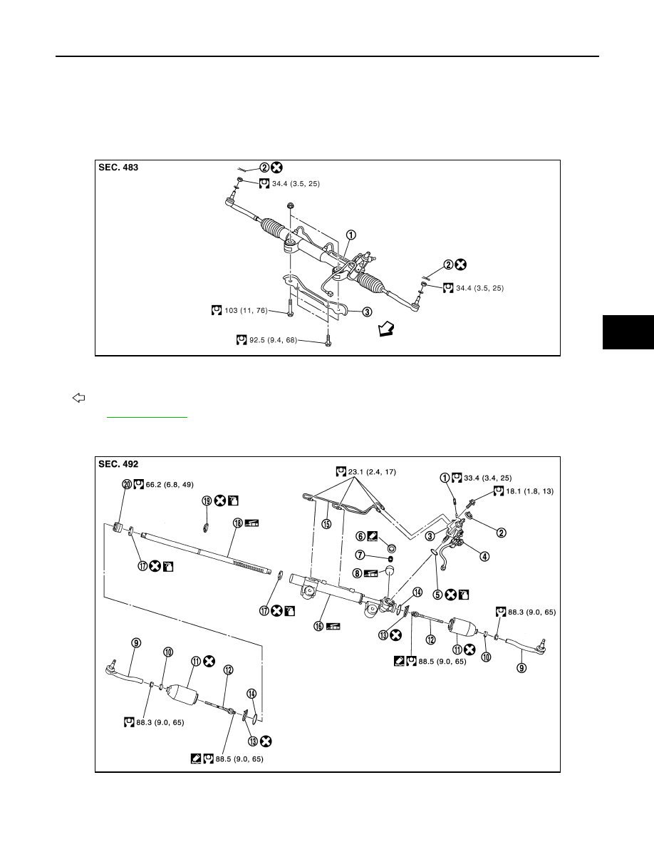
2WD : Exploded View
INFOID:0000000003134399
REMOVAL
DISASSEMBLY
1.
Steering gear assembly
2.
Cotter pin
3.
Rack stay
: Vehicle front
Refer to
JSGIA0038GB
1.
Low pressure piping
2.
Rear cover cap
3.
Gear-sub assembly
4.
Power steering solenoid valve
5.
O-ring
6.
Adjusting screw
JSGIA0359GB
ST-26
< ON-VEHICLE REPAIR >
STEERING GEAR AND LINKAGE
2WD : Removal and Installation
INFOID:0000000003134400
REMOVAL
1.
Set the vehicle to the straight-ahead position.
2.
Remove tires with a power tool.
3.
Remove front suspension member stay. Refer to
.
4.
Remove engine lower cover. Refer to
.
5.
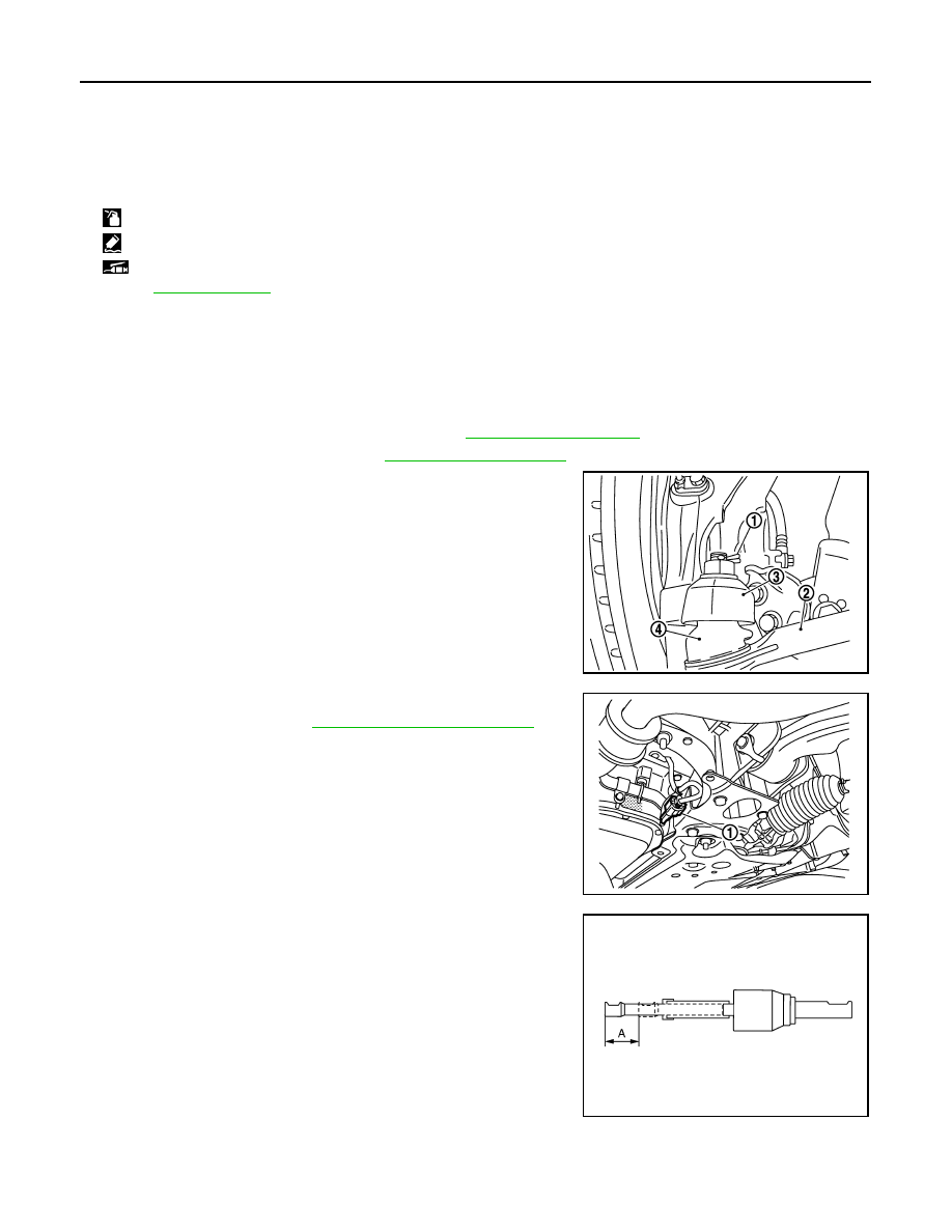
Remove cotter pin (1), and then loosen the nut.
6.
Remove steering outer socket (2) from steering knuckle (3) so
as not to damage ball joint boot (4) using suitable ball joint
remover.
CAUTION:
Temporarily tighten the nut to prevent damage to threads
and to prevent the ball joint remover from suddenly coming
off.
7.
Remove high pressure piping and low pressure piping of
hydraulic piping, and then drain power steering fluid.
8.
Remove power steering solenoid valve harness connector (1).
9.
Remove rack stay. Refer to
10. Remove lower joint fixing bolt (steering gear side).
11. Separate the lower shaft from the steering gear assembly by
sliding the side shaft (A: sliding range).
CAUTION:
Spiral cable may be cut if steering wheel turns while sepa-
rating steering column assembly and steering gear assem-
bly. Be sure to secure steering wheel using string to avoid
turning.
12. Remove steering gear assembly.
INSTALLATION
Note the following, and install in the reverse order of removal.
CAUTION:
7.
Spring
8.
Retainer
9.
Outer socket
10. Boot clamp
11.
Boot
12. Inner socket
13. Boot clamp (stainless wire)
14. Spacer
15. Cylinder tubes
16. Gear housing assembly
17. Rack oil seal
18. Rack assembly
19. Rack Teflon ring
20. End cover assembly
: Apply power steering fluid.
: Apply Genuine Liquid Gasket, Three Bond 1111B or equivalent.
: Apply multi-purpose grease.
Refer to
for symbols not described on the above.
PGIA0063E
JSGIA0360ZZ
JSGIA0035ZZ
STEERING GEAR AND LINKAGE
ST-27
< ON-VEHICLE REPAIR >
C
D
E
F
H
I
J
K
L
M
A
B
ST
N
O
P
Spiral cable may be cut if steering wheel turns while separating steering column assembly and steer-
ing gear assembly. Be sure to secure steering wheel using string to avoid turning.
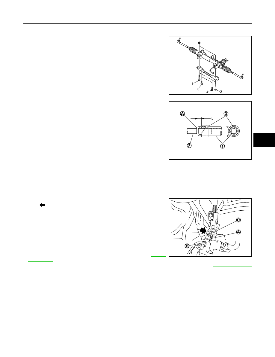
• Tighten the mounting bolts in the order shown in the figure when
installing the steering gear assembly.
• When installing suction hoses (1), refer to the figure.
CAUTION:
• Never apply fluid to the hose (1) and tube (2).
• Insert hose securely until it contacts spool (A) of tube.
• Leave clearance (L) when installing clamp (3).
• When installing lower joint to steering gear assembly, follow the procedure listed below.
- Set rack of steering gear in the neutral position.
NOTE:
To get the neutral position of rack, turn gear-sub assembly and measure the distance of inner socket, and
then measure the intermediate position of the distance.
- Align rear cover cap projection (A) with the marking position of gear housing assembly (B).
- Install slit part of lower joint (C) aligning with the rear cover cap
projection (A). Make sure that the slit part of lower joint (C) is
aligned with rear cover cap projection (A) and the marking position
of gear housing assembly (B).
• After installation, bleed air from the steering hydraulic system.
.
• Perform final tightening of nuts and bolts on each part under
unladen conditions with tires on level ground when removing steer-
ing gear assembly. Check wheel alignment. Refer to
• Adjust neutral position of steering angle sensor after checking wheel alignment. Refer to
MENT OF STEERING ANGLE SENSOR NEUTRAL POSITION : Special Repair Requirement"
2WD : Disassembly and Assembly
INFOID:0000000003562729
DISASSEMBLY
1.
Remove low pressure piping.
CAUTION:
• Disassemble and assemble steering gear assembly by fixing the mounting area with a vise using
copper plates.
• Clean steering gear assembly with kerosene before disassembling. Be careful to avoid splash-
ing or applying any kerosene over connector of discharge port or return port.
2.
Remove cylinder tubes from gear housing assembly.
3.
Remove rear cover cap from gear-sub assembly.
Temporary tightening: 1
⇒
2
⇒
3
⇒
4
Final tightening: 1
⇒
2
⇒
3
⇒
4
JSGIA0112ZZ
Standard
L
: 3 – 8 mm (0.12 – 0.31 in)
JSGIA0118ZZ
: Bolt
JSGIA0111ZZ
ST-28
< ON-VEHICLE REPAIR >
STEERING GEAR AND LINKAGE
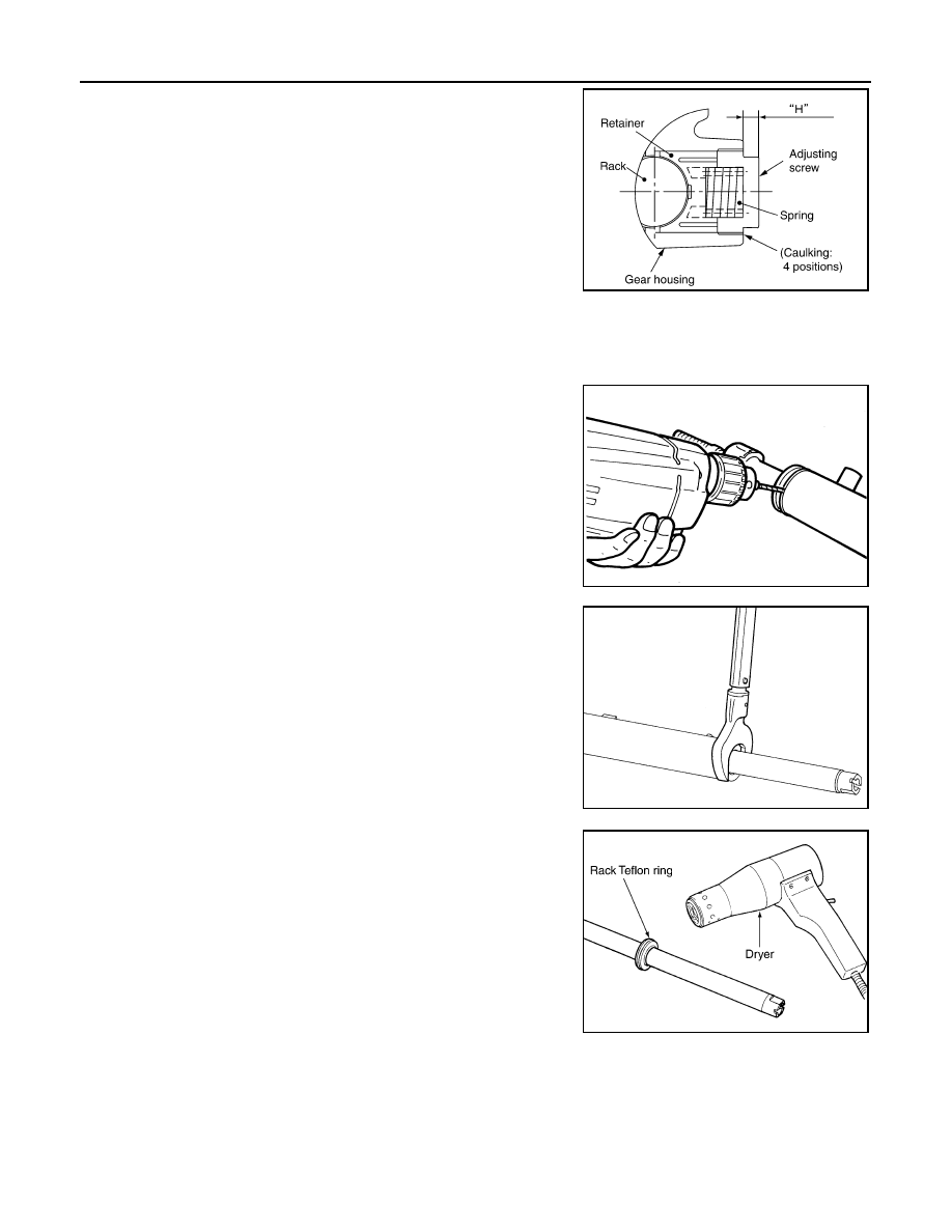
4.
Measure adjusting screw height “H”, and loosen adjusting
screw.
CAUTION:
• Never loosen adjusting screw 2 turns or more.
• Replace steering gear assembly if adjusting screw is
loosened 2 turns or more and it is removed.
5.
Remove gear-sub assembly from gear housing assembly.
6.
Remove O-ring from gear housing assembly.
7.
Loosen outer socket lock nut, and remove outer socket.
8.
Remove boot clamps, and then remove boot from inner socket.
CAUTION:
Never damage inner socket and gear housing assembly when removing boot. Inner socket and
gear housing assembly must be replaced if inner socket and gear housing assembly are damaged
because it may cause foreign material interfusion.
9.
Remove inner socket from gear housing assembly.
10. Drill out the clinching part of gear housing assembly (end cover
assembly side) outer rim with a 3 mm (0.12 in) drill bit. [Drill for
approximately 1.5 mm (0.059 in) depth.]
11. Remove end cover assembly with a 36 mm (1.42 in) open head
(suitable tool).
CAUTION:
Never damage rack assembly surface when removing. Rack
assembly must be replaced if damaged because it may
cause fluid leakage.
12. Pull rack assembly together with rack oil seal (outer side) out
from gear housing assembly.
CAUTION:
Never damage cylinder inner wall when remove rack
assembly. Gear housing assembly must be replaced if dam-
aged because it may cause fluid leakage.
13. Heat rack Teflon ring to approximately 40
°
C (104
°
F) with a
dryer, and remove rack Teflon ring from rack assembly.
CAUTION:
Never damage rack assembly. Rack assembly must be
replaced if damaged because it may cause fluid leakage.
SGIA0624E
STC0013D
SST081B
SGIA0151E
Нет комментариевНе стесняйтесь поделиться с нами вашим ценным мнением.
Текст