Infiniti EX35. Manual — part 1385
STEERING COLUMN
ST-21
< ON-VEHICLE REPAIR >
C
D
E
F
H
I
J
K
L
M
A
B
ST
N
O
P
10. Remove combination meter. Refer to
.
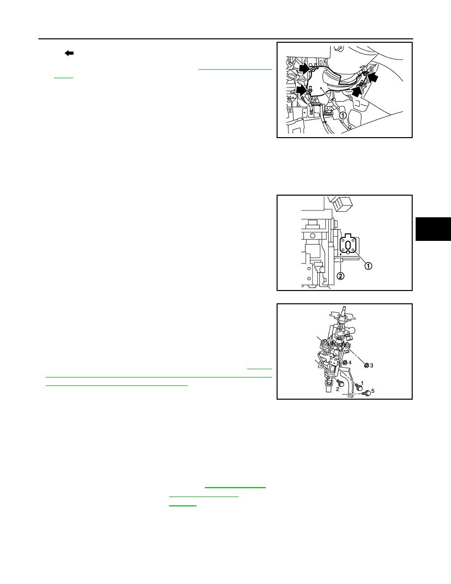
11. Disconnect each switch harness connectors installed to steering
column assembly.
12. Remove the upper joint mounting bolt and nut (lower shaft side),
and separate the joint from lower shaft.
13. Remove steering column assembly.
CAUTION:
• Never give axial impact to steering column assembly dur-
ing removal.
• Never move steering gear assembly when removing steering column assembly.
• Never rotate the lower shaft.
INSTALLATION
Note the following, and install in the reverse order of removal.
• Make sure there is no space between clip (1) and steering column
assembly (2).
• Tighten the mounting bolts in the order shown in the figure when
installing the steering column assembly.
CAUTION:
• Never give axial impact to steering column assembly during
installation.
• Never move steering gear assembly.
• Never reuse the joint mounting nut (lower shaft side).
• Adjust neutral position of steering angle sensor. Refer to
"ADJUSTMENT OF STEERING ANGLE SENSOR NEUTRAL
POSITION : Special Repair Requirement"
WITH ELECTRIC MOTOR : Inspection
INFOID:0000000003134391
INSPECTION AFTER REMOVAL
• Check each part of steering column assembly for damage or other malfunctions. Replace if necessary.
• Measure steering column assembly rotating torque using a preload gauge [SST: ST3127S000 (J-25765-A)].
Replace steering column assembly if outside the standard.
: Bolt
JSGIA0344ZZ
JSGIA0354ZZ
JSGIA0353ZZ
Standard
Rotating torque
: Refer to
ST-22
< ON-VEHICLE REPAIR >
STEERING COLUMN
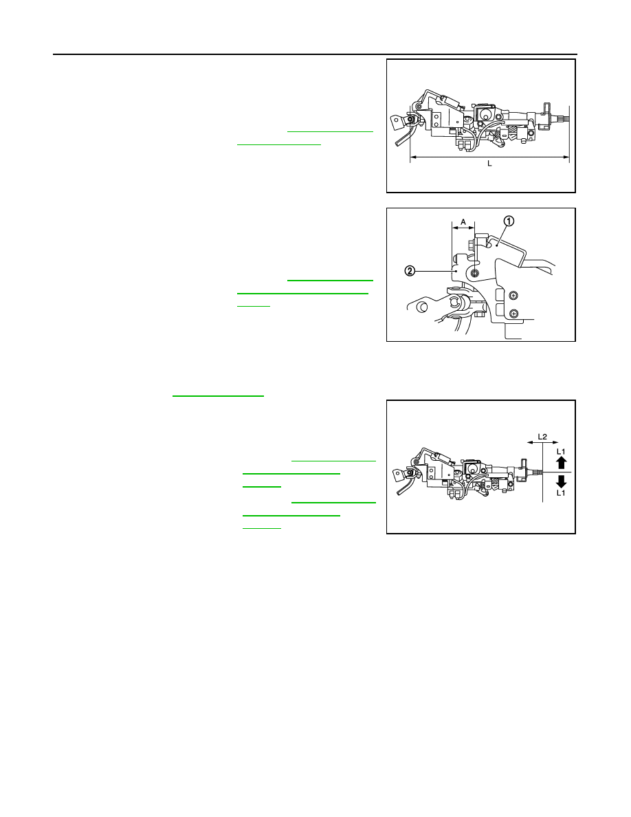
• Measure the length (L) as shown, if vehicle has been involved in a
minor collision. Replace steering column assembly if out side the
standard.
• Install the bracket (1) and steering column housing (2) so that the
clearance (A) is within the specified range as described below.
Replace steering column assembly if out side the standard.
INSPECTION AFTER INSTALLATION
• Check each part of steering column assembly for damage or other malfunctions. Replace if necessary.
• Check the steering wheel play, neutral position steering wheel, steering wheel turning force, and front wheel
turning angle. Refer to
.
• Check tilt and telescopic mechanism operating range tilt operating
range (L1), telescopic operating range (L2) as shown in the figure.
Standard
L
: Refer to
.
JSGIA0355ZZ
Standard
A
: Refer to
JSGIA0351ZZ
Standard
L1
: Refer to
L2
: Refer to
JSGIA0356ZZ

LOWER SHAFT
ST-23
< ON-VEHICLE REPAIR >
C
D
E
F
H
I
J
K
L
M
A
B
ST
N
O
P
LOWER SHAFT
Exploded View
INFOID:0000000003134392
Removal and Installation
INFOID:0000000003134393
REMOVAL
1.
Set the vehicle to the straight-ahead position.
2.
Fix the steering wheel.
3.
Remove lower joint fixing bolt (steering gear side).
4.
Separate the lower shaft from the steering gear assembly by
sliding the slide shaft (A: sliding range).
CAUTION:
Spiral cable may be cut if steering wheel turns while sepa-
rating steering column assembly and steering gear assem-
bly. Be sure to secure steering wheel using string to avoid
turning.
5.
Remove the accelerator pedal bracket and lever assembly.
Refer to
6.
Remove the parking brake wire clamp stay.
7.
Remove the hole cover mounting nuts.
8.
Remove the upper joint fixing bolt and nut (lower shaft side).
9.
Remove the lower shaft and hole cover.
10. Remove collar, hole cover seal, clamp and hole cover.
INSTALLATION
Note the following, and install in the reverse order of removal.
CAUTION:
Spiral cable may be cut if steering wheel turns while separating steering column assembly and steer-
ing gear assembly. Be sure to secure steering wheel using string to avoid turning.
1.
Steering column assembly
2.
Collar
3.
Hole cover seal
4.
Clamp
5.
Hole cover
6.
Lower shaft
7.
Lower joint
Refer to
JSGIA0357GB
JSGIA0035ZZ

ST-24
< ON-VEHICLE REPAIR >
LOWER SHAFT
• Tighten the clamp to the specified torque and check the clamp
length (A).
• When installing lower joint to steering gear assembly, follow the
procedure listed below.
- Set rack of steering gear in the neutral position.
NOTE:
To get the neutral position of rack, turn gear-sub assembly and
measure the distance of inner socket, and then measure the inter-
mediate position of the distance.
- Align rear cover cap projection (A) with the marking position of
gear housing assembly (B).
- Install slit part of lower joint (C) aligning with the rear cover cap
projection (A). Make sure that the slit part of lower joint (C) is
aligned with rear cover cap projection (A) and the marking position
of gear housing assembly (B).
• Adjust neutral position of steering angle sensor. Refer to
"ADJUSTMENT OF STEERING ANGLE SENSOR NEUTRAL
POSITION : Special Repair Requirement"
.
• Check the following after installation:
- Check if steering wheel turns smoothly when it is turned several
times fully to the end of the left and right.
- Check the steering wheel play, neutral position steering wheel, steering wheel turning force, and front wheel
turning angle. Refer to
.
Inspection
INFOID:0000000003134394
• Check the length (A) (extended position) of the lower shaft.
• Check each part of lower shaft for damage or other malfunctions.
Replace if there are.
A
: 14.0 – 18.0 mm (0.551 – 0.709 in)
: Bolt
JSGIA0094ZZ
JSGIA0111ZZ
Standard
A
: Refer to
JSGIA0358ZZ
Нет комментариевНе стесняйтесь поделиться с нами вашим ценным мнением.
Текст