Infiniti EX35. Manual — part 536
DLN-94
< SERVICE DATA AND SPECIFICATIONS (SDS)
[REAR PROPELLER SHAFT: 3F80A-1VL107]
SERVICE DATA AND SPECIFICATIONS (SDS)
SERVICE DATA AND SPECIFICATIONS (SDS)
SERVICE DATA AND SPECIFICATIONS (SDS)
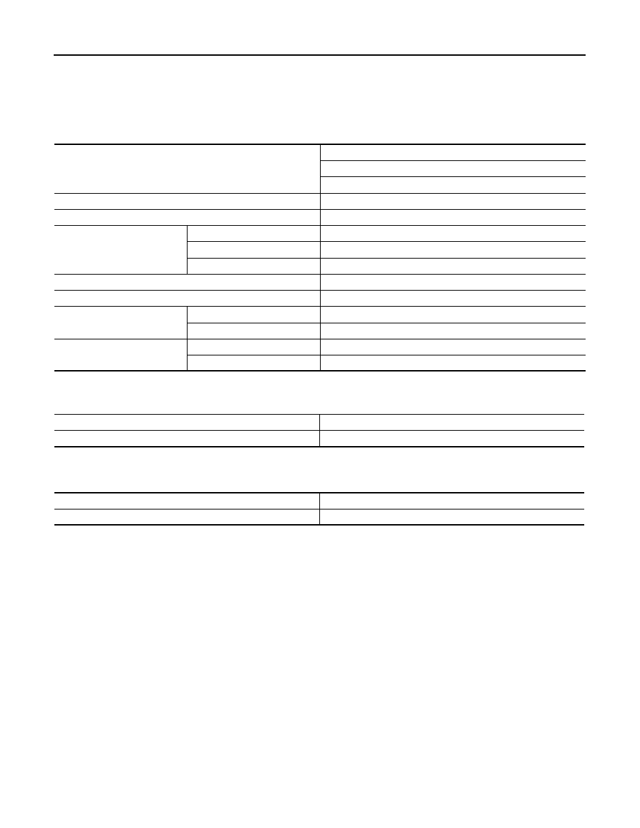
General Specifications
INFOID:0000000003135773
Propeller Shaft Runout
INFOID:0000000003135774
Unit: mm (in)
Journal Axial Play
INFOID:0000000003135775
Unit: mm (in)
Applied model
AWD
VQ35HR
A/T
Propeller shaft model
3F80A-1VL107
Number of joints
3
Type of journal bearings
(Non-disassembly type)
1st joint
Shell type
2nd joint
Shell type
3rd joint
Rebro joint type
Coupling method with transmission
Flange type
Coupling method with rear final drive
Rebro joint type
Shaft length
1st (Spider to spider)
378 mm (14.88 in)
2nd (Spider to spider)
723 mm (28.46 in)
Shaft outer diameter
1st
82.6 mm (3.252 in)
2nd
75.0 mm (2.953 in)
Item
Limit
Propeller shaft runout
0.8 (0.031)
Item
Standard
Journal axial play
0 (0)
NOISE, VIBRATION AND HARSHNESS (NVH) TROUBLESHOOTING
DLN-95
< SYMPTOM DIAGNOSIS >
[FRONT FINAL DRIVE: F160A]
C
E
F
G
H
I
J
K
L
M
A
B
DLN
N
O
P
SYMPTOM DIAGNOSIS
NOISE, VIBRATION AND HARSHNESS (NVH) TROUBLESHOOTING
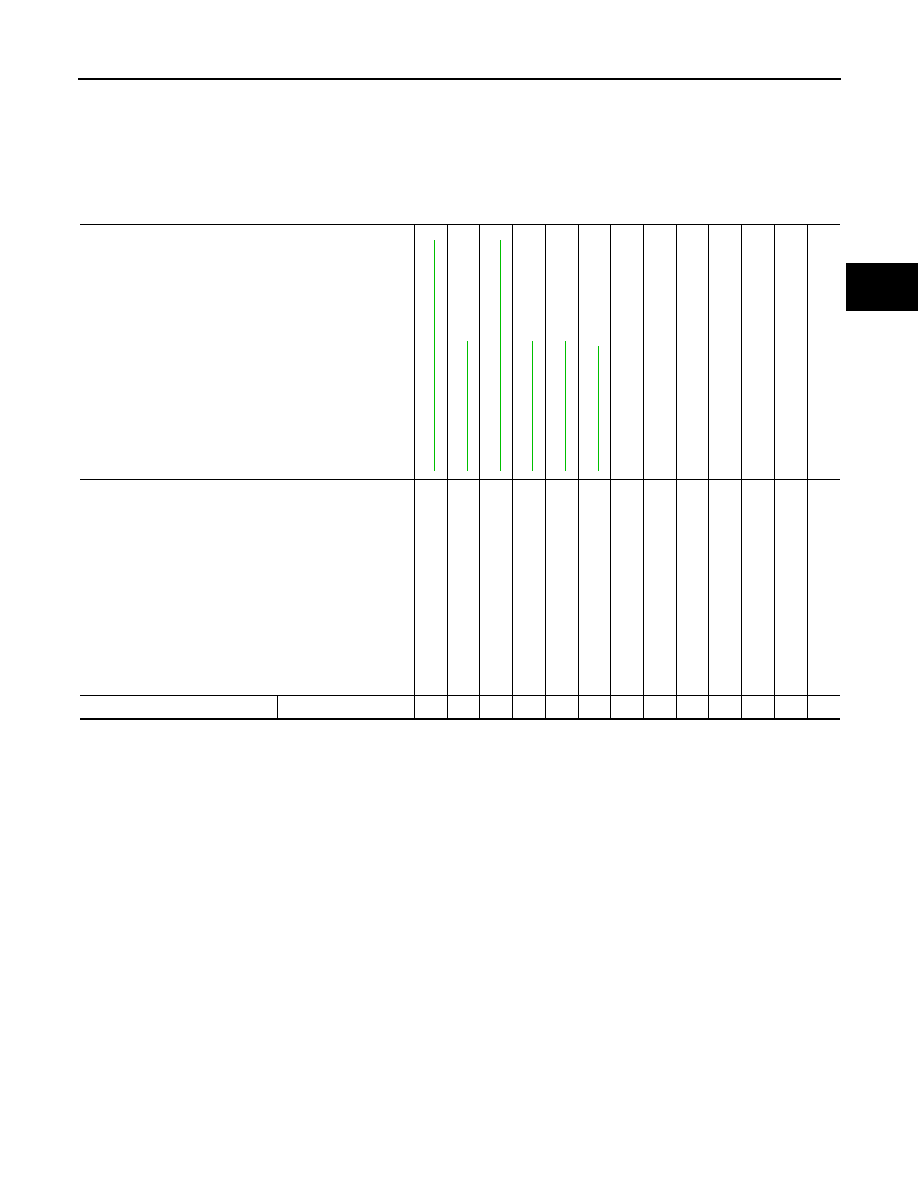
NVH Troubleshooting Chart
INFOID:0000000003135776
Use the chart below to help you find the cause of the symptom. If necessary, repair or replace these parts.
×
: Applicable
Reference
NVH in DLN
section.
NVH in F
AX, RAX
, FSU
and RSU sections.
NVH in WT
se
ct
io
n.
NVH in WT
se
ct
io
n.
NVH in F
AX and RAX section.
NVH in BR section.
NVH in ST
section.
Possible cause and SUSPECTED PARTS
Ge
ar t
o
ot
h ro
ug
h
Gea
r co
nt
ac
t im
pro
p
e
r
T
o
ot
h s
u
rf
ac
es
worn
Ba
ckl
a
s
h
i
n
co
rrect
Co
mp
an
io
n
f
lan
ge
ex
ces
si
ve
run
o
u
t
Gea
r oi
l im
p
rope
r
PROPELLER SHAF
T
AXLE AND SUSPE
NSION
TIRE
ROA
D
WHEEL
DRIVE SHA
F
T
BRAKE
STEERI
N
G
Symptom
Noise
×
×
×
×
×
×
×
×
×
×
×
×
×
DLN-96
< PRECAUTION >
[FRONT FINAL DRIVE: F160A]
PRECAUTIONS
PRECAUTION
PRECAUTIONS
Precaution Necessary for Steering Wheel Rotation after Battery Disconnect
INFOID:0000000003135777
NOTE:
• Before removing and installing any control units, first turn the push-button ignition switch to the LOCK posi-
tion, then disconnect both battery cables.
• After finishing work, confirm that all control unit connectors are connected properly, then re-connect both
battery cables.
• Always use CONSULT-III to perform self-diagnosis as a part of each function inspection after finishing work.
If a DTC is detected, perform trouble diagnosis according to self-diagnostic results.
This vehicle is equipped with a push-button ignition switch and a steering lock unit.
If the battery is disconnected or discharged, the steering wheel will lock and cannot be turned.
If turning the steering wheel is required with the battery disconnected or discharged, follow the procedure
below before starting the repair operation.
OPERATION PROCEDURE
1.
Connect both battery cables.
NOTE:
Supply power using jumper cables if battery is discharged.
2.
Carry the Intelligent Key or insert it to the key slot and turn the push-button ignition switch to ACC position.
(At this time, the steering lock will be released.)
3.
Disconnect both battery cables. The steering lock will remain released with both battery cables discon-
nected and the steering wheel can be turned.
4.
Perform the necessary repair operation.
5.
When the repair work is completed, re-connect both battery cables. With the brake pedal released, turn
the push-button ignition switch from ACC position to ON position, then to LOCK position. (The steering
wheel will lock when the push-button ignition switch is turned to LOCK position.)
6.
Perform self-diagnosis check of all control units using CONSULT-III.
Service Notice or Precautions for Front Final Drive
INFOID:0000000003135778
CAUTION:
• Check for the correct installation status prior to removal or disassembly. If matching marks are
required, be certain they never interfere with the function of the parts when applied.
• Overhaul should be done in a clean work area, it is preferable to work in dustproof area.
• Before disassembly, using steam or white gasoline, completely remove sand and mud from the exte-
rior of the unit, preventing them from entering into the unit during disassembly or assembly.
• Check appearance of the disassembled parts for damage, deformation, and unusual wear. Replace
them with a new ones if necessary.
• Gaskets, seals and O-rings should be replaced any time when the unit is disassembled.
• In principle, tighten bolts or nuts gradually in several steps working diagonally from inside to out-
side. If tightening sequence is specified, observe it.
• Clean and flush the parts sufficiently and blow-dry them.
• Be careful not to damage sliding surfaces and mating surfaces.
• When applying sealant, remove the old sealant from the mounting surface; then remove any mois-
ture, oil, and foreign materials from the application and mounting surfaces.
• Always use shop paper for cleaning the inside of components.
• Avoid using cotton gloves or shop rags to prevent entering of lint.
• During assembly, observe the specified tightening torque, and apply new gear oil, petroleum jelly, or
multi-purpose grease as specified for each vehicle, if necessary.
NOTE:
Front oil seal cannot be replaced on vehicle, because there is not enough room.

PREPARATION
DLN-97
< PREPARATION >
[FRONT FINAL DRIVE: F160A]
C
E
F
G
H
I
J
K
L
M
A
B
DLN
N
O
P
PREPARATION
PREPARATION
Special Service Tools
INFOID:0000000003135779
The actual shapes of Kent-Moore tools may differ from those of special service tools illustrated here.
Tool number
(Kent-Moore No.)
Tool name
Description
KV381054S0
(J-34286)
Puller
• Removing side oil seal (right side)
• Removing side bearing outer race
ST33400001
(J-26082)
Drift
a: 60 mm (2.36 in) dia.
b: 47 mm (1.85 in) dia.
• Installing side oil seal (right side)
• Installing front oil seal
KV38102100
(J-25803-01)
Drift
a: 44 mm (1.73 in) dia.
b: 36 mm (1.42 in) dia.
c: 24.5 mm (0.965 in) dia.
Installing side oil seal (left side)
KV38100200
(
—
)
Drift
a: 65 mm (2.56 in) dia.
b: 49 mm (1.93 in) dia.
Installing side shaft oil seal
ST30032000
(J-26010-01)
Drift
a: 80 mm (3.15 in) dia.
b: 38 mm (1.50 in) dia.
c: 31 mm (1.22 in) dia.
• Installing side shaft
• Installing pinion rear bearing inner race
KV10111100
(J-37228)
Seal cutter
Removing carrier cover
ZZA0601D
ZZA0702D
ZZA1046D
ZZA1143D
S-NT107
S-NT046
Нет комментариевНе стесняйтесь поделиться с нами вашим ценным мнением.
Текст