Infiniti EX35. Manual — part 535
DLN-90
< ON-VEHICLE REPAIR >
[REAR PROPELLER SHAFT: 3F80A-1VL107]
REAR PROPELLER SHAFT
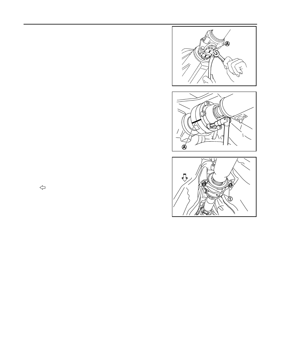
5.
Put matching marks (A) on propeller shaft flange yoke and
transfer companion flange.
CAUTION:
For matching marks, use paint. Never damage propeller
shaft flange yoke and transfer companion flange.
6.
Put matching marks (A) on propeller shaft rebro joint and final
drive companion flange.
CAUTION:
For matching marks, use paint. Never damage propeller
shaft rebro joint and final drive companion flange.
7.
Loosen mounting nuts (1) of center bearing mounting brackets
(upper/lower).
CAUTION:
Tighten mounting nuts temporarily.
8.
Remove propeller shaft assembly fixing bolts and nuts.
9.
Remove center bearing mounting bracket fixing nuts.
10. Remove propeller shaft assembly.
CAUTION:
• Never damage the rear oil seal of transmission.
• If constant velocity joint was bent during propeller shaft assembly removal, installation, or trans-
portation, its boot may be damaged. Wrap boot interference area to metal part with shop cloth or
rubber to protect boot from breakage.
INSTALLATION
Note the following, and install in the reverse order of removal.
JPDID0207ZZ
JPDID0208ZZ
: Vehicle front
JPDID0187ZZ
REAR PROPELLER SHAFT
DLN-91
< ON-VEHICLE REPAIR >
[REAR PROPELLER SHAFT: 3F80A-1VL107]
C
E
F
G
H
I
J
K
L
M
A
B
DLN
N
O
P
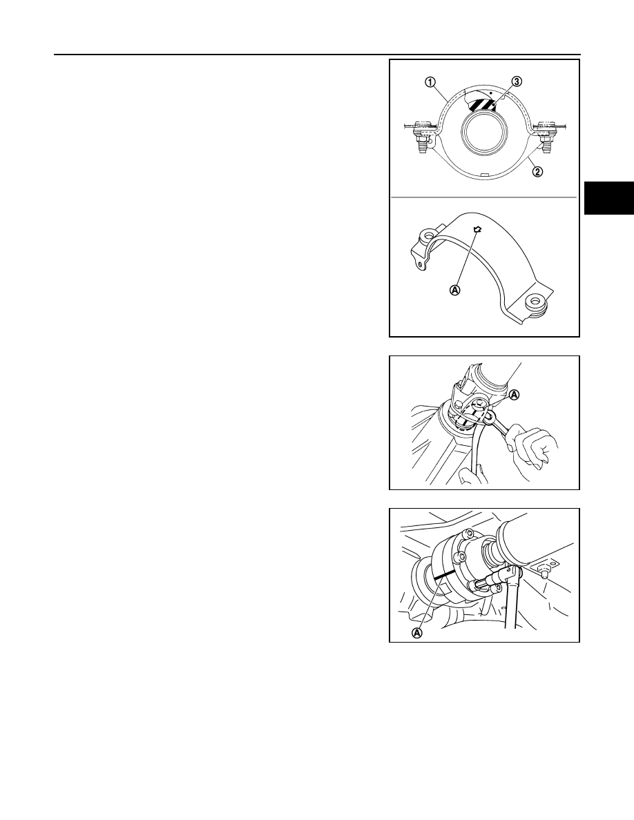
• Install center bearing mounting bracket (upper) (1) with its arrow
mark (A) facing forward.
• Adjust position of center bearing mounting bracket (upper), center
bearing mounting bracket (lower) (2) sliding back and forth to pre-
vent play in thrust direction of center bearing insulator (3). Install
center bearing mounting bracket (upper/lower) to vehicle.
• Align matching marks (A) to install propeller shaft flange yoke and
transfer companion flange.
• Align matching marks (A) to install propeller shaft rebro joint and
final drive companion flange.
CAUTION:
JPDID0145ZZ
JPDID0207ZZ
JPDID0208ZZ

DLN-92
< ON-VEHICLE REPAIR >
[REAR PROPELLER SHAFT: 3F80A-1VL107]
REAR PROPELLER SHAFT
Tighten mounting bolt and nut in the order shown in the fig-
ure.
• After assembly, perform a driving test to check propeller shaft
vibration. If vibration occurred, separate propeller shaft from final
drive. Reinstall companion flange after rotating it by 60, 120, 180,
240, 300 degrees. Then perform driving test and check propeller
shaft vibration again at each point.
• If propeller shaft or final drive has been replaced, connect them as
follows:
- Install the propeller shaft while aligning its matching mark (A) with
the matching mark (B) on the joint as close as possible.
CAUTION:
• Avoid damaging the rebro joint boot, protect it with a shop
towel or equivalent.
• Tighten mounting bolt and nut in the order shown in the fig-
ure.
Inspection
INFOID:0000000003135772
APPEARANCE
Check propeller shaft for bend and damage. If damage is detected, replace propeller shaft assembly.
PROPELLER SHAFT RUNOUT
Check propeller shaft runout at measuring points with a dial indica-
tor. If runout exceeds specifications, replace propeller shaft assem-
bly. For measuring point, refer to
JOURNAL AXIAL PLAY
JPDID0204ZZ
SDIA2049E
JPDID0204ZZ
Limit
Propeller shaft runout
JSDIA0079ZZ
REAR PROPELLER SHAFT
DLN-93
< ON-VEHICLE REPAIR >
[REAR PROPELLER SHAFT: 3F80A-1VL107]
C
E
F
G
H
I
J
K
L
M
A
B
DLN
N
O
P
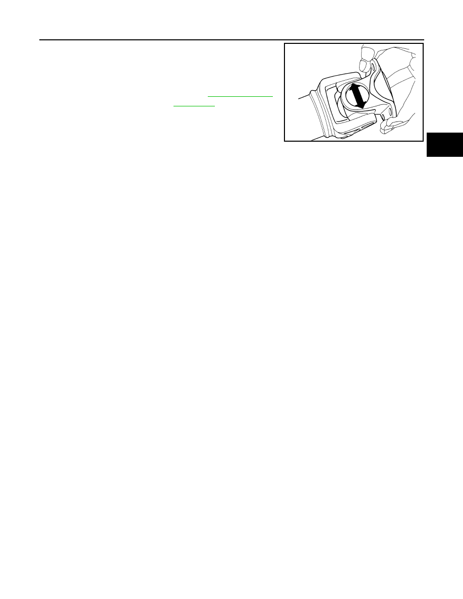
As shown in the figure, while fixing yoke on one side, check axial
play of joint. If it is outside the standard, replace propeller shaft
assembly.
CAUTION:
Never disassemble joints.
CENTER BEARING
Check center bearing for noise and damage. If noise or damage is detected, replace propeller shaft assembly.
CAUTION:
Never disassemble center bearing.
Standard
Journal axial play
: Refer to
PDA0005D
Нет комментариевНе стесняйтесь поделиться с нами вашим ценным мнением.
Текст