Infiniti EX35. Manual — part 1242
RSU-10
< ON-VEHICLE REPAIR >
REAR SHOCK ABSORBER
REAR SHOCK ABSORBER
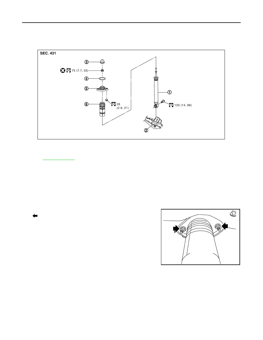
Exploded View
INFOID:0000000003130381
Removal and Installation
INFOID:0000000003130382
REMOVAL
1.
Remove tires with power tool.
2.
Set suitable jack under axle assembly to relieve the coil spring tension.
3.
Remove shock absorber (lower side) with power tool.
4.
Gradually lower the jack to remove it from rear lower link.
5.
Remove shock absorber assembly mounting nuts (upper side)
(
), and then remove shock absorber assembly.
INSTALLATION
Note the following, and install in the reverse order of removal.
• Perform final tightening of bolts and nuts at the shock absorber lower side (rubber bushing), under unladen
conditions with tires on level ground.
Disassembly and Assembly
INFOID:0000000003130383
DISASSEMBLY
CAUTION:
Never damage shock absorber piston rod when removing components from shock absorber.
1.
Remove cap from mounting bracket
1.
Shock absorber
2.
Front lower link
3.
Cap
4.
Mounting seal
5.
Shock absorber mounting bracket
6.
Bound bumper cover
Refer to
for symbols in the figure.
JPEIB0090GB
JPEIB0100ZZ
REAR SHOCK ABSORBER
RSU-11
< ON-VEHICLE REPAIR >
C
D
F
G
H
I
J
K
L
M
A
B
RSU
N
O
P
2.
Wrap a shop cloth around lower side of shock absorber and fix it with a vise.
CAUTION:
Never set the cylindrical part of shock absorber with a vise.
3.
Secure the piston rod tip so that piston rod does not turn, and remove piston rod lock nut.
4.
Remove mounting seal, mounting bracket and bound bumper cover from shock absorber.
ASSEMBLY
Install in the reverse order of disassembly.
Inspection
INFOID:0000000003130384
INSPECTION AFTER REMOVAL
Check the following items, and replace the parts if necessary.
• Shock absorber assembly for deformation, cracks, damage.
• Welded and sealed areas for oil leakage.
INSPECTION AFTER INSTALLATION
1.
Check wheel alignment. Refer to
2.
Adjust neutral position of steering angle sensor. Refer to
BRC-8, "ADJUSTMENT OF STEERING ANGLE
SENSOR NEUTRAL POSITION : Special Repair Requirement"
.
INSPECTION AFTER DISASSEMBLY
Bound Bumper and Bushing
Check bound bumper cover and bushing for cracks and damage. Replace it if necessary.
Shock Absorber
Check the following items, and replace the part if necessary.
• Shock absorber for deformation, cracks, and other damage.
• Piston rod for damage, uneven wear, and distortion.
INSPECTION AFTER ASSEMBLY
Make sure piston rod on shock absorber is not damaged when attaching components to shock absorber.

RSU-12
< ON-VEHICLE REPAIR >
SUSPENSION ARM
SUSPENSION ARM
Exploded View
INFOID:0000000003130385
Removal and Installation
INFOID:0000000003130386
REMOVAL
1.
Remove tire with power tool.
2.
Remove radius rod. Refer to
3.
Remove caliper assembly mounting bolts with power tool. Hang torque member in a place where it will not
interfere with work. Refer to
BR-40, "BRAKE CALIPER ASSEMBLY : Exploded View"
.
4.
Set suitable jack under axle assembly to relieve the coil spring tension.
5.
Remove stabilizer connecting rod. Refer to
.
6.
Remove drive shaft. Refer to
7.
Remove height sensor (with xenon head lamp). Refer to
.
8.
Remove cotter pin of suspension arm ball joint, and loosen nut. Refer to
.
9.
Remove suspension arm mounting bolts and nuts (rear suspension member side).
10. Use the ball joint remover to remove suspension arm from axle housing. Be careful not to damage ball
joint boot.
CAUTION:
Tighten temporarily mounting nut to prevent damage to threads and to prevent ball joint remover
from coming off.
11. Remove suspension arm.
12. Remove stabilizer connecting rod mounting bracket. Refer to
INSTALLATION
Note the following and, install in the reverse order of removal.
• Perform final tightening of rear suspension member installation position (rubber bussing), under unladen
conditions with tires on level ground.
Inspection
INFOID:0000000003130387
INSPECTION AFTER REMOVAL
Appearance
1.
Suspension arm
2.
Stopper rubber
3.
Rear suspension member
Refer to
for symbols in the figure.
JPEIB0091GB
SUSPENSION ARM
RSU-13
< ON-VEHICLE REPAIR >
C
D
F
G
H
I
J
K
L
M
A
B
RSU
N
O
P
Check the following items, and replace the part if necessary.
• Suspension arm and bushing for deformation, cracks or damage.
• Boot of ball joint for cracks or damage, and also for grease leakage.
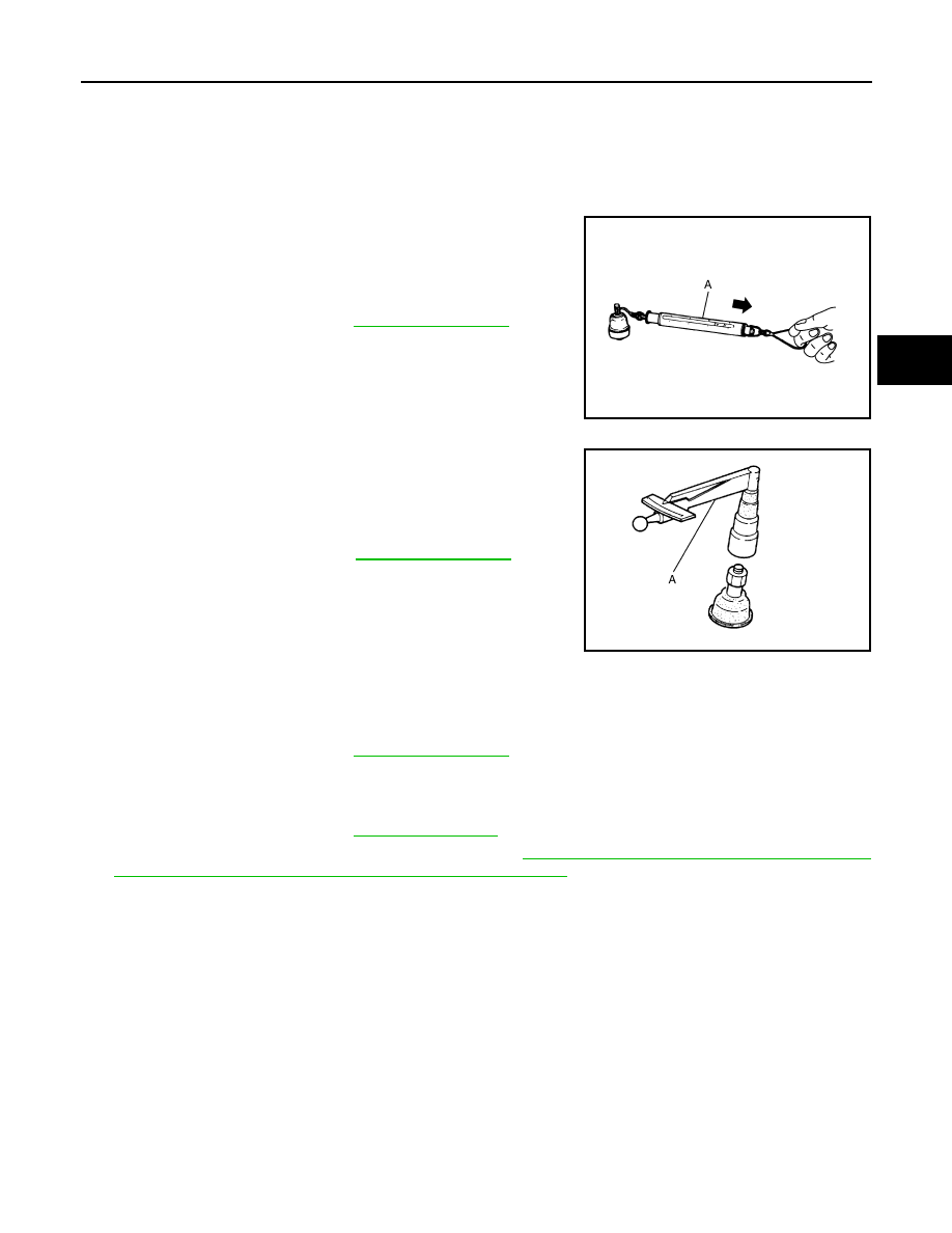
Ball Joint Inspection
Manually move ball stud at least ten times by hand to check for smooth movement.
Swing Torque Inspection
• Hook spring balance (A) at cotter pin mounting hole. Confirm
spring balance measurement value is within specifications when
ball stud begins moving.
- If swing torque exceeds the standard range, replace suspension
arm assembly.
Rotating Torque Inspection
• Attach the mounting nut to ball stud. Make sure that rotating torque
is within the specifications with a preload gauge (A) [SST:
ST3127S000 (J-25765-A)].
- If rotating torque exceeds the standard range, replace suspension
arm assembly.
Axial End Play Inspection
• Move tip of ball stud in axial direction to check for looseness.
- If axial end play exceeds the standard range, replace suspension arm assembly.
INSPECTION AFTER INSTALLATION
1.
Check wheel alignment. Refer to
2.
Adjust neutral position of steering angle sensor. Refer to
BRC-8, "ADJUSTMENT OF STEERING ANGLE
SENSOR NEUTRAL POSITION : Special Repair Requirement"
.
Standard
Swing torque
: Refer to
.
JPEIA0005ZZ
Standard
Rotating torque
: Refer to
PDIA1258E
Standard
Axial end play
: Refer to
.
Нет комментариевНе стесняйтесь поделиться с нами вашим ценным мнением.
Текст