Infiniti EX35. Manual — part 1243
RSU-14
< ON-VEHICLE REPAIR >
RADIUS ROD
RADIUS ROD
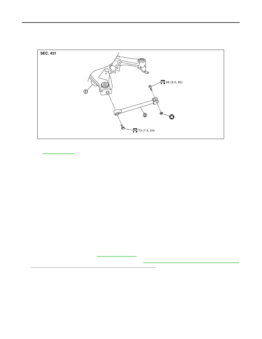
Exploded View
INFOID:0000000003130388
Removal and Installation
INFOID:0000000003130389
REMOVAL
1.
Remove tire with power tool.
2.
Remove radius rod mounting bolt and nut (axle housing side) with power tool.
3.
Remove radius rod mounting bolt (rear suspension member side) with power tool, and remove radius rod.
INSTALLATION
Note the following, and install in the reverse order of removal.
• Perform final tightening of rear suspension member and axle installation position (rubber bushing), under
unladen conditions with tires on level ground.
Inspection
INFOID:0000000003130390
INSPECTION AFTER REMOVAL
Check radius rod and bushing for any deformation, cracks, or damage. Replace it if necessary.
INSPECTION AFTER INSTALLATION
1.
Check wheel alignment. Refer to
2.
Adjust neutral position of steering angle sensor. Refer to
BRC-8, "ADJUSTMENT OF STEERING ANGLE
SENSOR NEUTRAL POSITION : Special Repair Requirement"
.
1.
Rear suspension member
2.
Radius rod
Refer to
for symbols in the figure.
JPEIB0092GB
FRONT LOWER LINK
RSU-15
< ON-VEHICLE REPAIR >
C
D
F
G
H
I
J
K
L
M
A
B
RSU
N
O
P
FRONT LOWER LINK
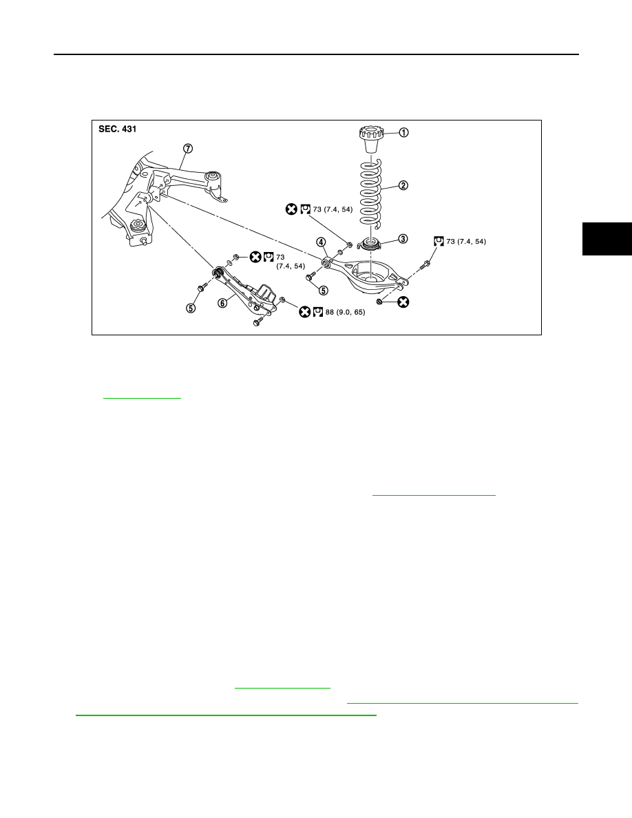
Exploded View
INFOID:0000000003579573
Removal and Installation
INFOID:0000000003130392
REMOVAL
1.
Remove tire with power tool.
2.
Set suitable jack under axle assembly to relieve the coil spring tension.
3.
Remove shock absorber mounting bolts (lower side). Refer to
.
4.
Remove front lower link mounting bolts and nuts (rear suspension member side) with power tool.
5.
Remove front lower link mounting bolts and nuts (axle housing side) with power tool, and remove front
lower link.
INSTALLATION
Note the following, and install in the reverse order of removal.
• Perform final tightening of rear suspension member and axle installation position (rubber bushing), under
unladen conditions with tires on level ground.
Inspection
INFOID:0000000003130393
INSPECTION AFTER REMOVAL
Check front lower link and bushing for any deformation, cracks, or damage. Replace it if necessary.
INSPECTION AFTER INSTALLATION
1.
Check wheel alignment. Refer to
2.
Adjust neutral position of steering angle sensor. Refer to
BRC-8, "ADJUSTMENT OF STEERING ANGLE
SENSOR NEUTRAL POSITION : Special Repair Requirement"
.
1.
Upper seat
2.
Coil spring
3.
Rubber seat
4.
Rear lower link
5.
Adjusting bolt
6.
Front lower link
7.
Rear suspension member
for symbols in the figure.
JPEIB0089GB
RSU-16
< ON-VEHICLE REPAIR >
REAR STABILIZER
REAR STABILIZER
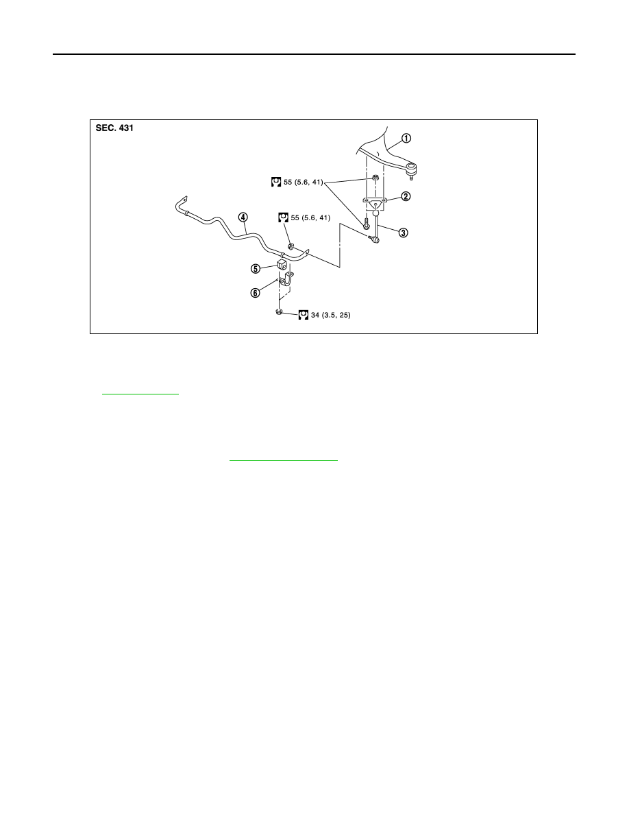
Exploded View
INFOID:0000000003130394
Removal and Installation
INFOID:0000000003130395
REMOVAL
1.
Remove center muffler. Refer to
2.
Remove under cover.
3.
Remove stabilizer connecting rod mounting nuts (lower side), and remove stabilizer connecting rod from
stabilizer bar with power tool.
4.
Remove stabilizer connecting rod mounting nuts (upper side), and remove stabilizer connecting rod from
stabilizer connecting rod mounting bracket with power tool.
5.
Remove mounting nuts on stabilizer clamp and remove stabilizer bar with power tool.
6.
Remove stabilizer connecting rod mounting bracket.
INSTALLATION
Note the following, and install in the reverse order of removal.
• Tighten the mounting nut to the specified torque while holding a hexagonal part of stabilizer connecting rod
side.
Inspection
INFOID:0000000003130396
INSPECTION AFTER REMOVAL
Check stabilizer bar, stabilizer connecting rod, stabilizer bushing and stabilizer clamp for deformation, cracks
or damage. Replace it if necessary.
1.
Suspension arm
2.
Stabilizer connecting rod mounting
bracket
3.
Stabilizer connecting rod
4.
Stabilizer bar
5.
Stabilizer bushing
6.
Stabilizer clamp
Refer to
for symbols in the figure.
JPEIB0093GB
REAR SUSPENSION MEMBER
RSU-17
< REMOVAL AND INSTALLATION >
C
D
F
G
H
I
J
K
L
M
A
B
RSU
N
O
P
REMOVAL AND INSTALLATION
REAR SUSPENSION MEMBER
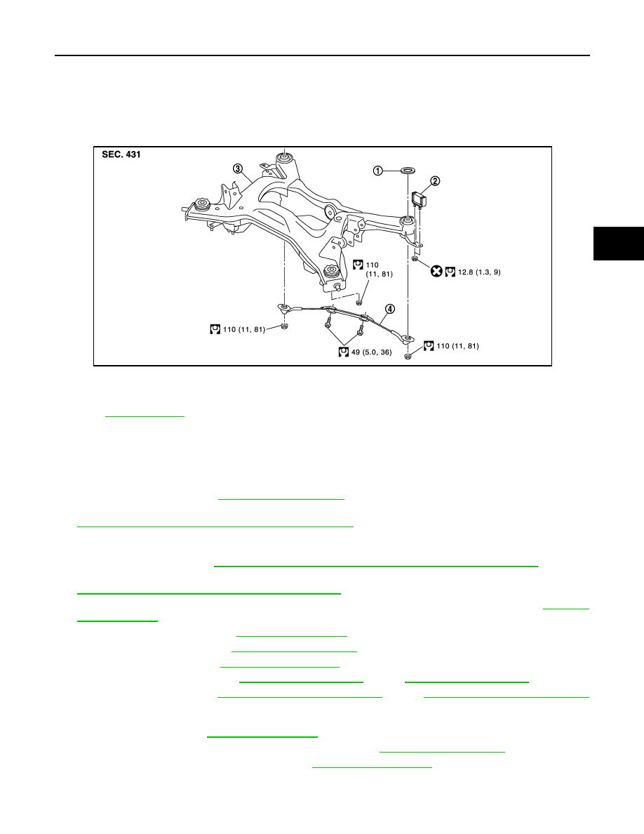
Exploded View
INFOID:0000000003130397
Removal and Installation
INFOID:0000000003130398
REMOVAL
1.
Remove tires with power tool.
2.
Remove radius rod. Refer to
3.
Remove caliper assembly with power tool. Hang it in a place where it will not interfere with work. Refer to
BR-40, "BRAKE CALIPER ASSEMBLY : Exploded View"
CAUTION:
Avoid depressing brake pedal while brake caliper is removed.
4.
Remove disc rotor. Refer to
BR-41, "BRAKE CALIPER ASSEMBLY : Removal and Installation"
.
5.
Remove wheel sensor and sensor harness from rear suspension member and suspension arm. Refer to
BRC-108, "REAR WHEEL SENSOR : Exploded View"
6.
Remove height sensor harness from rear suspension member (with xenon head lamp). Refer to
7.
Remove center muffler. Refer to
8.
Remove stabilizer bar. Refer to
9.
Remove drive shaft. Refer to
10. Remove propeller shaft. Refer to
(2WD),
(AWD).
11. Remove final drive. Refer to
DLN-160, "2WD : Exploded View"
DLN-161, "AWD : Exploded View"
(AWD).
12. Remove parking brake cable mounting bolt and separate parking brake cable from vehicle and rear sus-
pension member. Refer to
.
13. Remove shock absorber mounting bolts (lower side). Refer to
.
14. Remove rear lower link and coil spring. Refer to
15. Remove under cover.
16. Set suitable jack under rear suspension member.
1.
Mount stopper
2.
Dynamic damper
3.
Rear suspension member
4.
Pin stay
for symbols in the figure.
JPEIB0094GB
Нет комментариевНе стесняйтесь поделиться с нами вашим ценным мнением.
Текст