Infiniti EX35. Manual — part 299
BCS
COMBINATION SWITCH INPUT CIRCUIT
BCS-43
< COMPONENT DIAGNOSIS >
C
D
E
F
G
H
I
J
K
L
B
A
O
P
N
4.
CHECK BCM INPUT SIGNAL
1.
Connect the combination switch connector.
2.
Turn ON any switch in the system that is malfunctioning.
3.
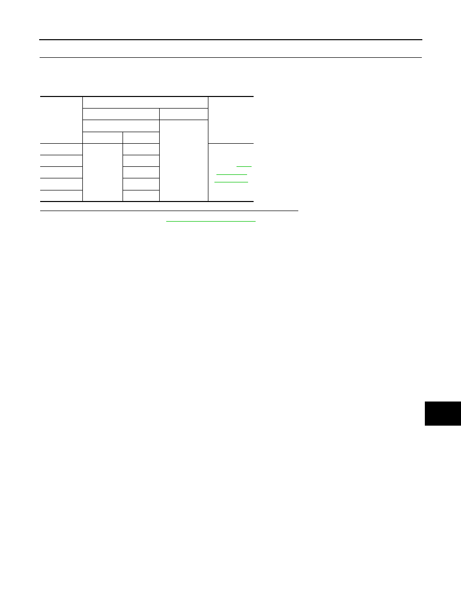
Check voltage between BCM harness connector and ground.
Is the measurement value normal when any of the switches is turned ON?
YES
>> Replace BCM. Refer to
NO
>> Replace the combination switch.
System
Terminals
Voltage
(Approx.)
(+)
(
−
)
BCM
Ground
Connector
Terminal
INPUT 1
M122
107
Refer to
INPUT 2
109
INPUT 3
88
INPUT 4
108
INPUT 5
87
BCS-44
< COMPONENT DIAGNOSIS >
COMBINATION SWITCH OUTPUT CIRCUIT
COMBINATION SWITCH OUTPUT CIRCUIT
Diagnosis Procedure
INFOID:0000000003137951
1.
CHECK OUTPUT 1 - 5 SYSTEM CIRCUIT FOR OPEN
1.
Turn the ignition switch OFF.
2.
Disconnect the BCM and combination switch connectors.
NOTE:
BCM connector disconnects M123 only.
3.
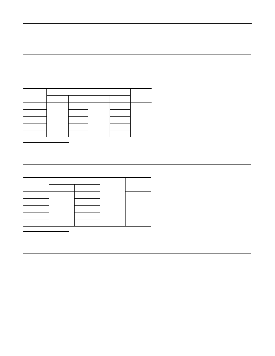
Check continuity between BCM harness connector and combination switch harness connector.
Does continuity exist?
YES
>> GO TO 2.
NO
>> Repair the harnesses or connectors.
2.
CHECK OUTPUT 1 - 5 SYSTEM CIRCUIT FOR SHORT
Check for continuity between BCM harness connector and ground.
Does continuity exist?
YES
>> Repair the harnesses or connectors.
NO
>> GO TO 3.
3.
CHECK COMBINATION SWITCH INTERNAL CIRCUIT
1.
Connect the combination switch connector.
2.
Turn ON any switch in the system that is malfunctioning.
3.
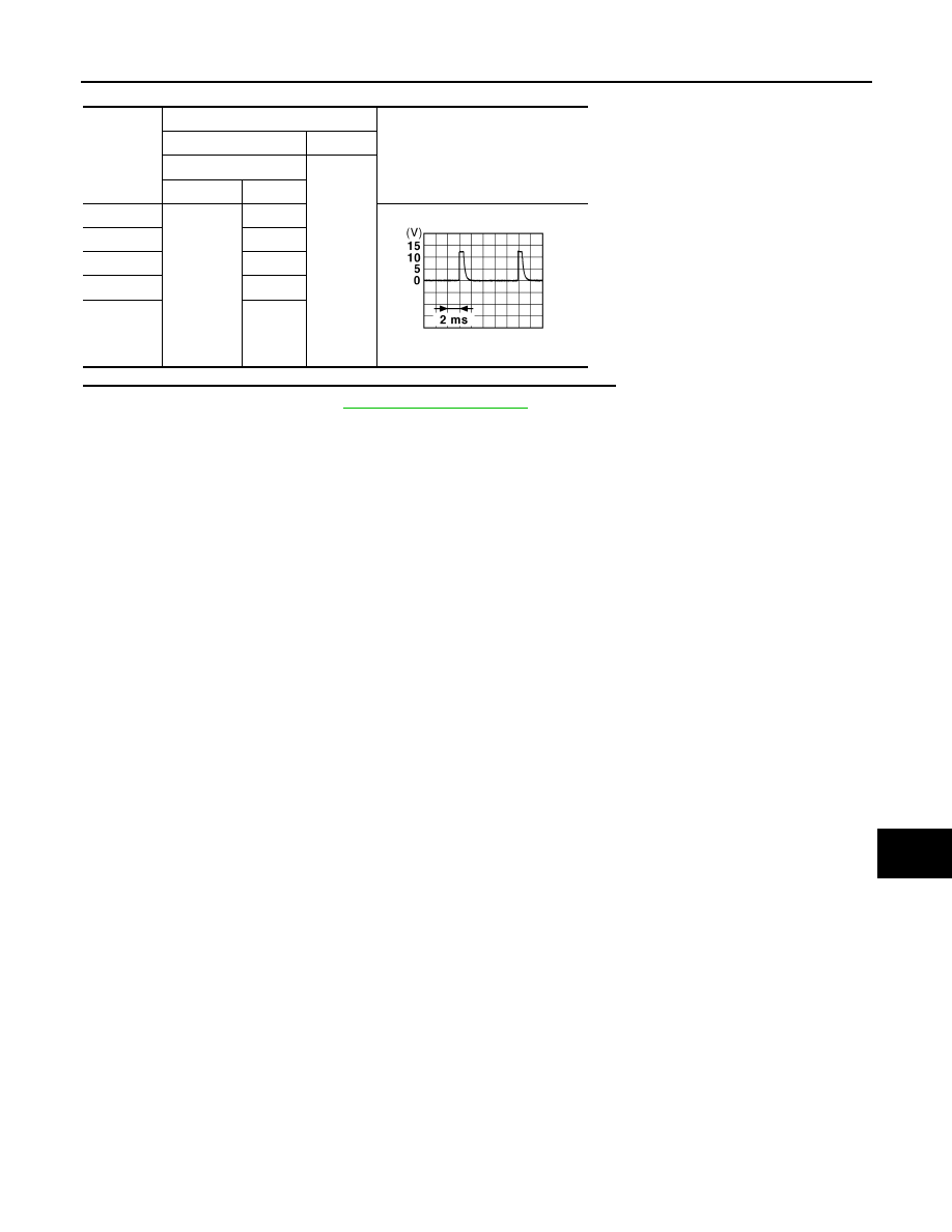
Check voltage between combination switch harness connector and ground.
NOTE:
Check that the combination switch outputs a signal from combination switch input system.
System
BCM
Combination switch
Continuity
Connector
Terminal
Connector
Terminal
OUTPUT 1
M123
143
M33
12
Existed
OUTPUT 2
144
14
OUTPUT 3
145
5
OUTPUT 4
146
2
OUTPUT 5
142
8
System
BCM
Ground
Continuity
Connector
Terminal
OUTPUT 1
M123
143
Not existed
OUTPUT 2
144
OUTPUT 3
145
OUTPUT 4
146
OUTPUT 5
142
BCS
COMBINATION SWITCH OUTPUT CIRCUIT
BCS-45
< COMPONENT DIAGNOSIS >
C
D
E
F
G
H
I
J
K
L
B
A
O
P
N
Is the measurement value normal when any of the switches is turned ON?
YES
>> Replace BCM. Refer to
NO
>> Replace the combination switch.
System
Terminals
Value (Approx.)
(+)
(
−
)
Combination switch
Ground
Connector
Terminal
OUTPUT 1
M33
12
1.4 V
OUTPUT 2
14
OUTPUT 3
5
OUTPUT 4
2
OUTPUT 5
8
JPMIA0041GB

BCS-46
< ECU DIAGNOSIS >
BCM (BODY CONTROL MODULE)
ECU DIAGNOSIS
BCM (BODY CONTROL MODULE)
Reference Value
INFOID:0000000003528868
VALUES ON THE DIAGNOSIS TOOL
CONSULT-III MONITOR ITEM
Monitor Item
Condition
Value/Status
FR WIPER HI
Other than front wiper switch HI
Off
Front wiper switch HI
On
FR WIPER LOW
Other than front wiper switch LO
Off
Front wiper switch LO
On
FR WASHER SW
Front washer switch OFF
Off
Front washer switch ON
On
FR WIPER INT
Other than front wiper switch INT
Off
Front wiper switch INT
On
FR WIPER STOP
Front wiper is not in STOP position
Off
Front wiper is in STOP position
On
INT VOLUME
Wiper intermittent dial is in a dial position 1 - 7
Wiper intermittent dial position
RR WIPER ON
Other than rear wiper switch ON
Off
Rear wiper switch ON
On
RR WIPER INT
Other than rear wiper switch INT
Off
Rear wiper switch INT
On
RR WASHER SW
Rear washer switch OFF
Off
Rear washer switch ON
On
RR WIPER STOP
Rear wiper is in STOP position
Off
Rear wiper is not in STOP position
On
TURN SIGNAL R
Other than turn signal switch RH
Off
Turn signal switch RH
On
TURN SIGNAL L
Other than turn signal switch LH
Off
Turn signal switch LH
On
TAIL LAMP SW
Other than lighting switch 1ST and 2ND
Off
Lighting switch 1ST or 2ND
On
HI BEAM SW
Other than lighting switch HI
Off
Lighting switch HI
On
HEAD LAMP SW 1
Other than lighting switch 2ND
Off
Lighting switch 2ND
On
HEAD LAMP SW 2
Other than lighting switch 2ND
Off
Lighting switch 2ND
On
PASSING SW
Other than lighting switch PASS
Off
Lighting switch PASS
On
AUTO LIGHT SW
Other than lighting switch AUTO
Off
Lighting switch AUTO
On
FR FOG SW
Front fog lamp switch OFF
Off
Front fog lamp switch ON
On
Нет комментариевНе стесняйтесь поделиться с нами вашим ценным мнением.
Текст