Infiniti EX35. Manual — part 298

BCS
U0415 VEHICLE SPEED SIG
BCS-39
< COMPONENT DIAGNOSIS >
C
D
E
F
G
H
I
J
K
L
B
A
O
P
N
U0415 VEHICLE SPEED SIG
Description
INFOID:0000000003137939
U0415 is displayed if any unusual condition is present in the reception status of the vehicle speed signal from
the ABS actuator and electric unit (control unit).
DTC Logic
INFOID:0000000003137940
DTC DETECTION LOGIC
DTC CONFIRMATION PROCEDURE
1.
DTC CONFIRMATION
1.
Erase the DTC.
2.
Turn ignition switch OFF.
3.
Perform the “Self Diagnostic Result” of CONSULT-III, when passed 2 seconds or more after the ignition
switch is turned ON.
Is any DTC detected?
YES
>> Refer to
NO
>> INSPECTION END
Diagnosis Procedure
INFOID:0000000003137941
1.
ABS ACTUATOR AND ELECTRIC UNIT (CONTROL UNIT) SELF-DIAG RESULTS
Perform “Self-Diagnostic Result” of ABS actuator and electric unit (control unit) with CONSULT-III. Refer to
BRC-30, "CONSULT-III Function"
Is any DTC detected?
YES
>> Repair or replace the malfunctioning part.
NO
>> Replace BCM. Refer to
.
DTC
CONSULT-III display
description
DTC Detection Condition
Probable cause
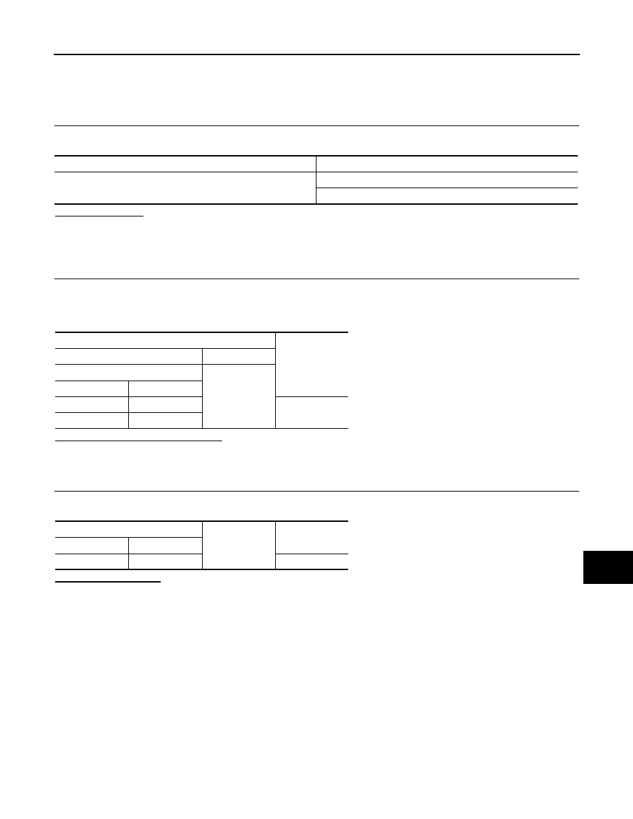
U0415
VEHICLE SPEED SIG
When the vehicle speed signal received from
the ABS actuator and electric unit (control
unit) remains abnormal for 2 seconds or more.
• ABS actuator and electric unit (control unit)
• BCM

BCS-40
< COMPONENT DIAGNOSIS >
B2562 LOW VOLTAGE
B2562 LOW VOLTAGE
DTC Logic
INFOID:0000000003137942
DTC DETECTION LOGIC
DTC CONFIRMATION PROCEDURE
1.
DTC CONFIRMATION
1.
Erase DTC.
2.
Turn ignition switch OFF.
3.
Perform the “Self Diagnostic Result” of CONSULT-III, when passed 1.5 seconds or more after the ignition
switch is turned ON.
Is any DTC detected?
YES
>> Refer to
.
NO
>> INSPECTION END
Diagnosis Procedure
INFOID:0000000003137943
1.
CHECK POWER SUPPLY CIRCUIT
Check BCM power supply circuit. Refer to
Is the circuit normal?
YES
>> Replace BCM. Refer to
NO
>> Repair the malfunctioning part.
DTC
CONSULT-III display
description
DTC Detection Condition
Possible cause
B2562
LOW VOLTAGE
When the power supply voltage to BCM remains less
than 8.8 V for 1.5 seconds or more
Harness or connector (power supply
circuit)
BCS
POWER SUPPLY AND GROUND CIRCUIT
BCS-41
< COMPONENT DIAGNOSIS >
C
D
E
F
G
H
I
J
K
L
B
A
O
P
N
POWER SUPPLY AND GROUND CIRCUIT
Diagnosis Procedure
INFOID:0000000003137948
1.
CHECK FUSE AND FUSIBLE LINK
Check that the following fuse and fusible link are not blown.
Is the fuse fusing?
YES
>> Replace the blown fuse or fusible link after repairing the affected circuit if a fuse or fusible link is
blown.
NO
>> GO TO 2.
2.
CHECK POWER SUPPLY CIRCUIT
1.
Turn ignition switch OFF.
2.
Disconnect BCM connectors.
3.
Check voltage between BCM harness connector and ground.
Is the measurement value normal?
YES
>> GO TO 3.
NO
>> Repair harness or connector.
3.
CHECK GROUND CIRCUIT
Check continuity between BCM harness connector and ground.
Does continuity exist?
YES
>> INSPECTION END
NO
>> Repair harness or connector.
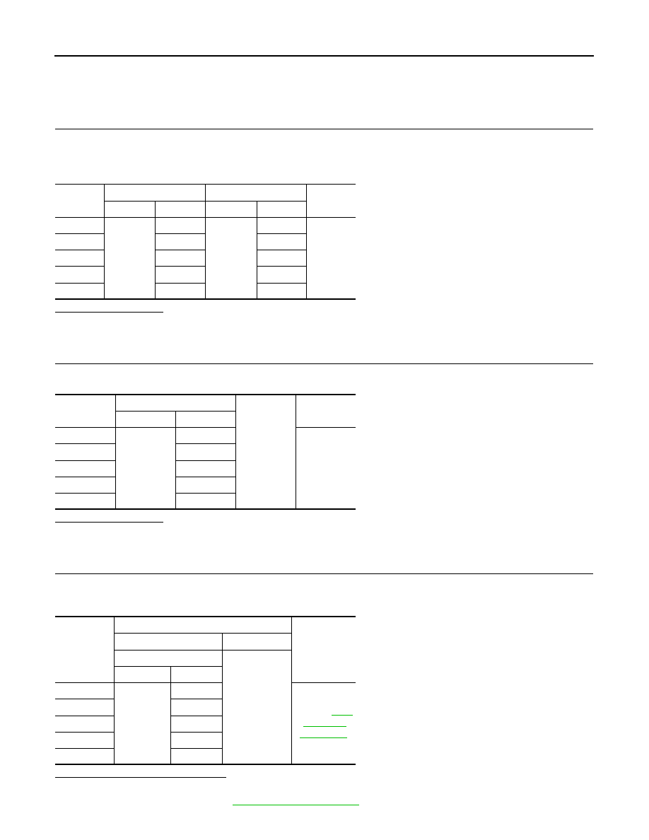
Signal name
Fuse and fusible link No.
Battery power supply
K
10
Terminals
Voltage
(Approx.)
(+)
(
−
)
BCM
Ground
Connector
Terminal
M118
1
Battery voltage
M119
11
BCM
Ground
Continuity
Connector
Terminal
M119
13
Existed
BCS-42
< COMPONENT DIAGNOSIS >
COMBINATION SWITCH INPUT CIRCUIT
COMBINATION SWITCH INPUT CIRCUIT
Diagnosis Procedure
INFOID:0000000003137949
1.
CHECK INPUT 1 - 5 SYSTEM CIRCUIT FOR OPEN
1.
Turn the ignition switch OFF.
2.
Disconnect the BCM and combination switch connectors.
3.
Check continuity between BCM harness connector and combination switch harness connector.
Does continuity exist?
YES
>> GO TO 2.
NO
>> Repair the harnesses or connectors.
2.
CHECK INPUT 1 - 5 SYSTEM CIRCUIT FOR SHORT
Check for continuity between BCM harness connector and ground.
Does continuity exist?
YES
>> Repair the harnesses or connectors.
NO
>> GO TO 3.
3.
CHECK BCM OUTPUT VOLTAGE
1.
Connect the BCM connector.
2.
Check voltage between BCM harness connector and ground.
Is the measurement value normal?
YES
>> GO TO 4.
NO
>> Replace BCM. Refer to
System
BCM
Combination switch
Continuity
Connector
Terminal
Connector
Terminal
INPUT 1
M122
107
M33
11
Existed
INPUT 2
109
9
INPUT 3
88
7
INPUT 4
108
10
INPUT 5
87
13
System
BCM
Ground
Continuity
Connector
Terminal
INPUT 1
M122
107
Not existed
INPUT 2
109
INPUT 3
88
INPUT 4
108
INPUT 5
87
System
Terminals
Voltage
(Approx.)
(+)
(
−
)
BCM
Ground
Connector
Terminal
INPUT 1
M122
107
Refer to
.
INPUT 2
109
INPUT 3
88
INPUT 4
108
INPUT 5
87
Нет комментариевНе стесняйтесь поделиться с нами вашим ценным мнением.
Текст