Infiniti EX35. Manual — part 595

EC-122
< FUNCTION DIAGNOSIS >
[VQ35HR]
ON BOARD DIAGNOSTIC (OBD) SYSTEM
*: Leaving cooling fan OFF with CONSULT-III while engine is running may cause the engine to overheat.
DTC & SRT CONFIRMATION MODE
SRT STATUS Mode
For details, refer to
EC-100, "Diagnosis Description"
.
SRT WORK SUPPORT Mode
This mode enables a technician to drive a vehicle to set the SRT while monitoring the SRT status.
DTC WORK SUPPORT Mode
*: DTC P1442 and P1456 does not apply to J50 models but appears in DTC Work Support Mode screens.
Diagnosis Tool Function
INFOID:0000000003133286
DESCRIPTION
EXT V/T ANGLE
• Engine: Return to the original
trouble condition
• Change exhaust valve timing us-
ing CONSULT-III.
If trouble symptom disappears, see
CHECK ITEM.
• Harness and connectors
• Exhaust valve timing control mag-
net retarder
FAN DUTY CON-
TROL*
• Ignition switch: ON
• Change duty ratio using CON-
SULT-III.
Cooling fan speed changes.
• Harness and connectors
• Cooling fan motor
• Cooling fan relay
• Cooling fan control module
• IPDM E/R
ALTERNATOR
DUTY
• Engine: Idle
• Change duty ratio using CON-
SULT-III.
Battery voltage changes.
• Harness and connectors
• IPDM E/R
• Alternator
TEST ITEM
CONDITION
JUDGMENT
CHECK ITEM (REMEDY)
Test mode
Test item
Corresponding DTC No.
Reference page
EVAPORATIVE SYSTEM
EVP SML LEAK P0442/P1442*
P0442
P0455
EVP V/S LEAK P0456/P1456*
P0456
PURG VOL CN/V P1444
P0443
PURG FLOW P0441
P0441
A/F SEN1
A/F SEN1 (B1) P1278/P1279
P0133
A/F SEN1 (B1) P1276
P0130
A/F SEN1 (B2) P1288/P1289
P0153
A/F SEN1 (B2) P1286
P0150
HO2S2
HO2S2 (B1) P1146
P0138
HO2S2 (B1) P1147
P0137
HO2S2 (B1) P0139
P0139
HO2S2 (B2) P1166
P0158
HO2S2 (B2) P1167
P0157
HO2S2 (B2) P0159
P0159
ON BOARD DIAGNOSTIC (OBD) SYSTEM
EC-123
< FUNCTION DIAGNOSIS >
[VQ35HR]
C
D
E
F
G
H
I
J
K
L
M
A
EC
N
P
O
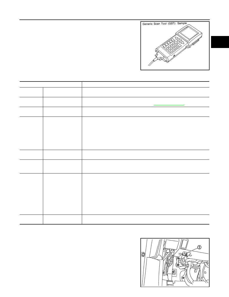
Generic Scan Tool (OBD II scan tool) complying with SAE J1978 has
8 different functions explained below.
ISO9141 is used as the protocol.
The name “GST” or “Generic Scan Tool” is used in this service man-
ual.
FUNCTION
INSPECTION PROCEDURE
1.
Turn ignition switch OFF.
2.
Connect “GST” to data link connector (1), which is located under
LH dash panel near the hood opener handle.
SEF139P
Diagnostic Service
Function
Service $01
READINESS TESTS
This diagnostic service gains access to current emission-related data values, including an-
alog inputs and outputs, digital inputs and outputs, and system status information.
Service $02
(FREEZE DATA)
This diagnostic service gains access to emission-related data value which were stored by
ECM during the freeze frame. For details, refer to
Service $03
DTCs
This diagnostic service gains access to emission-related power train trouble codes which
were stored by ECM.
Service $04
CLEAR DIAG INFO
This diagnostic service can clear all emission-related diagnostic information. This in-
cludes:
• Clear number of diagnostic trouble codes (Service $01)
• Clear diagnostic trouble codes (Service $03)
• Clear trouble code for freeze frame data (Service $01)
• Clear freeze frame data (Service $02)
• Reset status of system monitoring test (Service $01)
• Clear on board monitoring test results (Service $06 and $07)
Service $06
(ON BOARD TESTS)
This diagnostic service accesses the results of on board diagnostic monitoring tests of
specific components/systems that are not continuously monitored.
Service $07
(ON BOARD TESTS)
This diagnostic service enables the off board test drive to obtain test results for emission-
related powertrain components/systems that are continuously monitored during normal
driving conditions.
Service $08
—
This diagnostic service can close EVAP system in ignition switch ON position (Engine
stopped). When this diagnostic service is performed, EVAP canister vent control valve can
be closed.
In the following conditions, this diagnostic service cannot function.
• Low ambient temperature
• Low battery voltage
• Engine running
• Ignition switch OFF
• Low fuel temperature
• Too much pressure is applied to EVAP system
Service $09
(CALIBRATION ID)
This diagnostic service enables the off-board test device to request specific vehicle infor-
mation such as Vehicle Identification Number (VIN) and Calibration IDs.
JMBIA0055ZZ
EC-124
< FUNCTION DIAGNOSIS >
[VQ35HR]
ON BOARD DIAGNOSTIC (OBD) SYSTEM
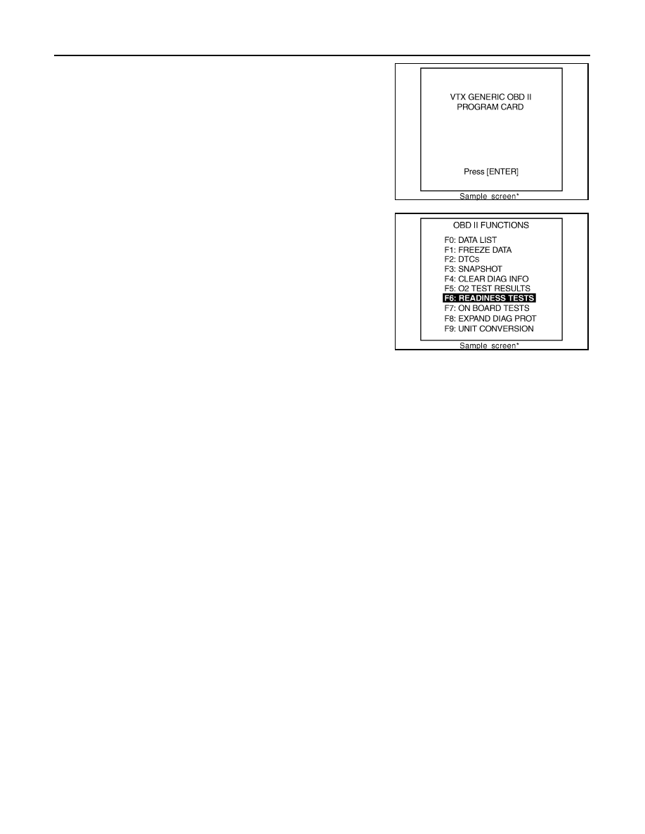
3.
Turn ignition switch ON.
4.
Enter the program according to instruction on the screen or in
the operation manual.
(*: Regarding GST screens in this section, sample screens are
shown.)
5.
Perform each diagnostic mode according to each service proce-
dure.
For further information, see the GST Operation Manual of
the tool maker.
SEF398S
SEF416S

TROUBLE DIAGNOSIS - SPECIFICATION VALUE
EC-125
< COMPONENT DIAGNOSIS >
[VQ35HR]
C
D
E
F
G
H
I
J
K
L
M
A
EC
N
P
O
COMPONENT DIAGNOSIS
TROUBLE DIAGNOSIS - SPECIFICATION VALUE
Description
INFOID:0000000003133287
The specification (SP) value indicates the tolerance of the value that is displayed in “SPEC” in “DATA MONI-
TOR” mode of CONSULT-III during normal operation of the Engine Control System. When the value in “SPEC”
in “DATA MONITOR” mode is within the SP value, the Engine Control System is confirmed OK. When the
value in “SPEC” in “DATA MONITOR” mode is NOT within the SP value, the Engine Control System may have
one or more malfunctions.
The SP value is used to detect malfunctions that may affect the Engine Control System, but will not light the
MIL.
The SP value will be displayed for the following three items:
• B/FUEL SCHDL (The fuel injection pulse width programmed into ECM prior to any learned on board correc-
tion)
• A/F ALPHA-B1/B2 (The mean value of air-fuel ratio feedback correction factor per cycle)
• MAS A/F SE-B1/B2 (The signal voltage of the mass air flow sensor)
Component Function Check
INFOID:0000000003133288
1.
PRECONDITIONING
Check that all of the following conditions are satisfied.
TESTING CONDITION
• Vehicle driven distance: More than 5,000 km (3,107 miles)
• Barometric pressure: 98.3 - 104.3 kPa (1.003 - 1.064 kg/cm
2
, 14.25 - 15.12 psi)
• Atmospheric temperature: 20 - 30
°
C (68 - 86
°
F)
• Engine coolant temperature: 75 - 95
°
C (167 - 203
°
F)
• Transmission: Warmed-up
- After the engine is warmed up to normal operating temperature, drive vehicle until “ATF TEMP SE 1” (A/T
fluid temperature sensor signal) indicates more than 60
°
C (140
°
F).
• Electrical load: Not applied
- Rear window defogger switch, air conditioner switch, lighting switch are OFF. Steering wheel is straight
ahead.
• Engine speed: Idle
>> GO TO 2.
2.
PERFORM SPEC IN DATA MONITOR MODE
With CONSULT-III
NOTE:
Perform “SPEC” in “DATA MONITOR” mode in maximum scale display.
1.
EC-12, "BASIC INSPECTION : Special Repair Requirement"
.
2.
Select “B/FUEL SCHDL”, “A/F ALPHA-B1”, “A/F ALPHA-B2”, “MAS A/F SE-B1” and “MAS A/F SE-B2” in
“SPEC” of “DATA MONITOR” mode with CONSULT-III.
3.
Check that monitor items are within the SP value.
Is the measurement value within the SP value?
YES
>> INSPECTION END
NO
>> Go to
Нет комментариевНе стесняйтесь поделиться с нами вашим ценным мнением.
Текст