Infiniti EX35. Manual — part 416
CHG-4
< BASIC INSPECTION >
DIAGNOSIS AND REPAIR WORKFLOW
NOTE:
To ensure a complete and thorough diagnosis, the battery, starter and alternator test segments must be done
as a set from start to finish.
1.
PRELIMINARY INSPECTION
Perform the preliminary inspection. Refer to
CHG-22, "Inspection Procedure"
.
>> GO TO 2.
2.
STOP POWER GENERATION VOLTAGE VARIABLE CONTROL SYSTEM
Stop the operation of the power generation voltage variable control in either of the following procedures.
• After selecting “ENGINE” of “SELECT SYSTEM” using CONSULT-III, set the DUTY value of “ALTERNATOR
DUTY” to 0 % by selecting “ALTERNATOR DUTY” of “Active Test”. Continue “Active Test” until the end of
inspection. (When the DUTY value is 0 or 100 %, the normal power generation is performed according to the
characteristic of the IC voltage regulator of the alternator.)
• Turn the ignition switch OFF, and disconnect the battery current sensor connector. [However, DTC (P1550 -
P1554) of the engine might remain. After finishing the inspection, connect the battery current sensor connec-
tor and erase the self-diagnosis results history of the engine using CONSULT-III.]
>> GO TO 3.
3.
DIAGNOSIS WITH STARTING/CHARGING SYSTEM TESTER
Perform the charging system test using Starting/Charging System Tester (SST: J-44373). For details and oper-
ating instructions, refer to Technical Service Bulletin.
Test result
CHARGING SYSTEM NORMAL>>Charging system is normal and will also show “DIODE RIPPLE” test
result.
NO CHARGING VOLTAGE>>GO TO 4.
LOW CHARGING VOLTAGE>>GO TO 12.
HIGH CHARGING VOLTAGE>>GO TO 14.
DIODE RIPPLE NORMAL>>Diode ripple is OK and will also show “CHARGING VOLTAGE” test result.
EXCESS RIPPLE DETECTED>>Replace the alternator. Perform “DIODE RIPPLE” test again using Starting/
Charging System Tester (SST: J-44373) to confirm repair.
DIODE RIPPLE NOT DETECTED>>GO TO 4.
4.
INSPECTION WITH CHARGE WARNING LAMP (IGNITION SWITCH IS ON)
Turn the ignition switch ON.
Does the charge warning lamp illuminate?
YES
>> GO TO 6.
NO
>> GO TO 5.
5.
“L” TERMINAL CIRCUIT (OPEN) INSPECTION
Check “L” terminal circuit (open). Refer to
Is the “L” terminal circuit normal?
YES
>> Replace alternator.
NO
>> Repair as needed.
6.
INSPECTION WITH CHARGE WARNING LAMP (IDLING)
Start the engine and run it at idle.
Does the charge warning lamp turn OFF?
YES
>> GO TO 9.
NO
>> GO TO 7.
7.
“L” TERMINAL CIRCUIT (SHORT) INSPECTION
Check “L” terminal circuit (short). Refer to
Is the “L” terminal circuit normal?
YES
>> GO TO 8.
NO
>> Repair as needed.
CHG
DIAGNOSIS AND REPAIR WORKFLOW
CHG-5
< BASIC INSPECTION >
C
D
E
F
G
H
I
J
K
L
B
A
O
P
N
8.
“S” TERMINAL CIRCUIT INSPECTION
Check “S” terminal circuit. Refer to
Is the “S” terminal circuit normal?
YES
>> GO TO 10.
NO
>> Repair as needed.
9.
INSPECTION WITH CHARGE WARNING LAMP (ENGINE AT 3,000 RPM)
Increase and maintain the engine speed at 3,000 rpm.
Does the charge warning lamp remain off?
YES
>> GO TO 11.
NO
>> GO TO 10.
10.
INSPECTION OF ALTERNATOR PULLEY
Check alternator pulley. Refer to
(2WD) or
(AWD).
Is alternator pulley normal?
YES
>> Replace alternator.
NO
>> Repair as needed.
11.
“B” TERMINAL CIRCUIT INSPECTION
Check “B” terminal circuit. Refer to
Is “B” terminal circuit normal?
YES
>> Replace alternator.
NO
>> Repair as needed.
12.
“B” TERMINAL CIRCUIT INSPECTION
Check “B” terminal circuit. Refer to
Is “B” terminal circuit normal?
YES
>> GO TO 13.
NO
>> Repair as needed.
13.
INSPECTION OF ALTERNATOR PULLEY
Check alternator pulley. Refer to
(2WD) or
(AWD).
Is alternator pulley normal?
YES
>> Replace alternator.
NO
>> Repair as needed.
14.
“S” TERMINAL CIRCUIT INSPECTION
Check “S” terminal circuit. Refer to
Is the “S” terminal circuit normal?
YES
>> Replace alternator.
NO
>> Repair as needed.
CHG-6
< FUNCTION DIAGNOSIS >
CHARGING SYSTEM
FUNCTION DIAGNOSIS
CHARGING SYSTEM
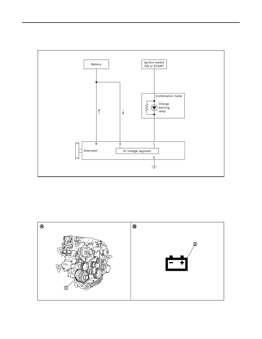
System Diagram
INFOID:0000000003131872
System Description
INFOID:0000000003131873
The alternator provides DC voltage to operate the vehicle's electrical system and to keep the battery charged.
The voltage output is controlled by the IC voltage regulator.
Component Parts Location
INFOID:0000000003131874
JPMIA0426GB
1.
Alternator
2.
Charge warning lamp
A.
Engine
B.
Combination meter
JSMIA0054ZZ

CHG
CHARGING SYSTEM
CHG-7
< FUNCTION DIAGNOSIS >
C
D
E
F
G
H
I
J
K
L
B
A
O
P
N
Component Description
INFOID:0000000003131875
Component part
Description
Alternator
The alternator provides DC voltage to operate the vehicle electri-
cal system and to keep the battery charged.
Combination meter (Charge warning lamp)
The IC voltage regulator warning function activates to illuminate
the charge warning lamp, if any of the following symptoms occur
while alternator is operating:
• Excessive voltage is produced.
• No voltage is produced.
Нет комментариевНе стесняйтесь поделиться с нами вашим ценным мнением.
Текст